
Open vessel sealing instrument with hourglass cutting mechanism and overratchet safety

a sealing instrument and cutting mechanism technology, applied in the field of forceps, can solve the problems of inability to safely coagulate arteries, ineffective vessel sealing purposes, and inconvenient operation, and achieve the effect of preventing the reciprocation of the cutting mechanism

Active Publication Date: 2014-01-07
COVIDIEN AG
View PDF1046 Cites 26 Cited by
  • Summary
  • Abstract
  • Description
  • Claims
  • Application Information

AI Technical Summary

Benefits of technology

The present invention is a special type of surgical forceps that can be used to seal tissue. It has two shafts with movable jaw tips that can grip tissue and use electrical energy to seal it. One of the jaws has a channel for a cutting mechanism that can be pushed forward to cut tissue. This forceps has a safety feature that prevents the cutting mechanism from moving when the jaws are first placed in position, and this feature is part of the cutting mechanism. Overall, this invention provides a special tool for surgeons to seal tissue with greater precision and safety.

Problems solved by technology

The article states that it is not possible to safely coagulate arteries with a diameter larger than 2 to 2.5 mm.
As can be appreciated, this additional step may be both time consuming (particularly when sealing a significant number of vessels) and may contribute to imprecise separation of the tissue along the sealing line due to the misalignment or misplacement of the severing instrument along the center of the tissue sealing line.
Other instruments include blade members or shearing members which simply cut tissue in a mechanical and / or electromechanical manner and are relatively ineffective for vessel sealing purposes.

Method used


Image

  • Open vessel sealing instrument with hourglass cutting mechanism and overratchet safety
  • Open vessel sealing instrument with hourglass cutting mechanism and overratchet safety
  • Open vessel sealing instrument with hourglass cutting mechanism and overratchet safety

Examples


Embodiment Construction

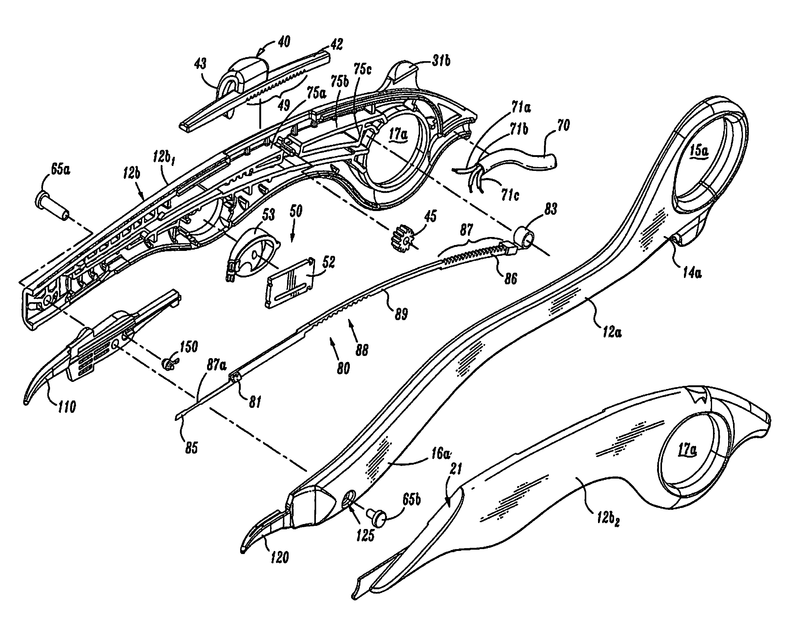
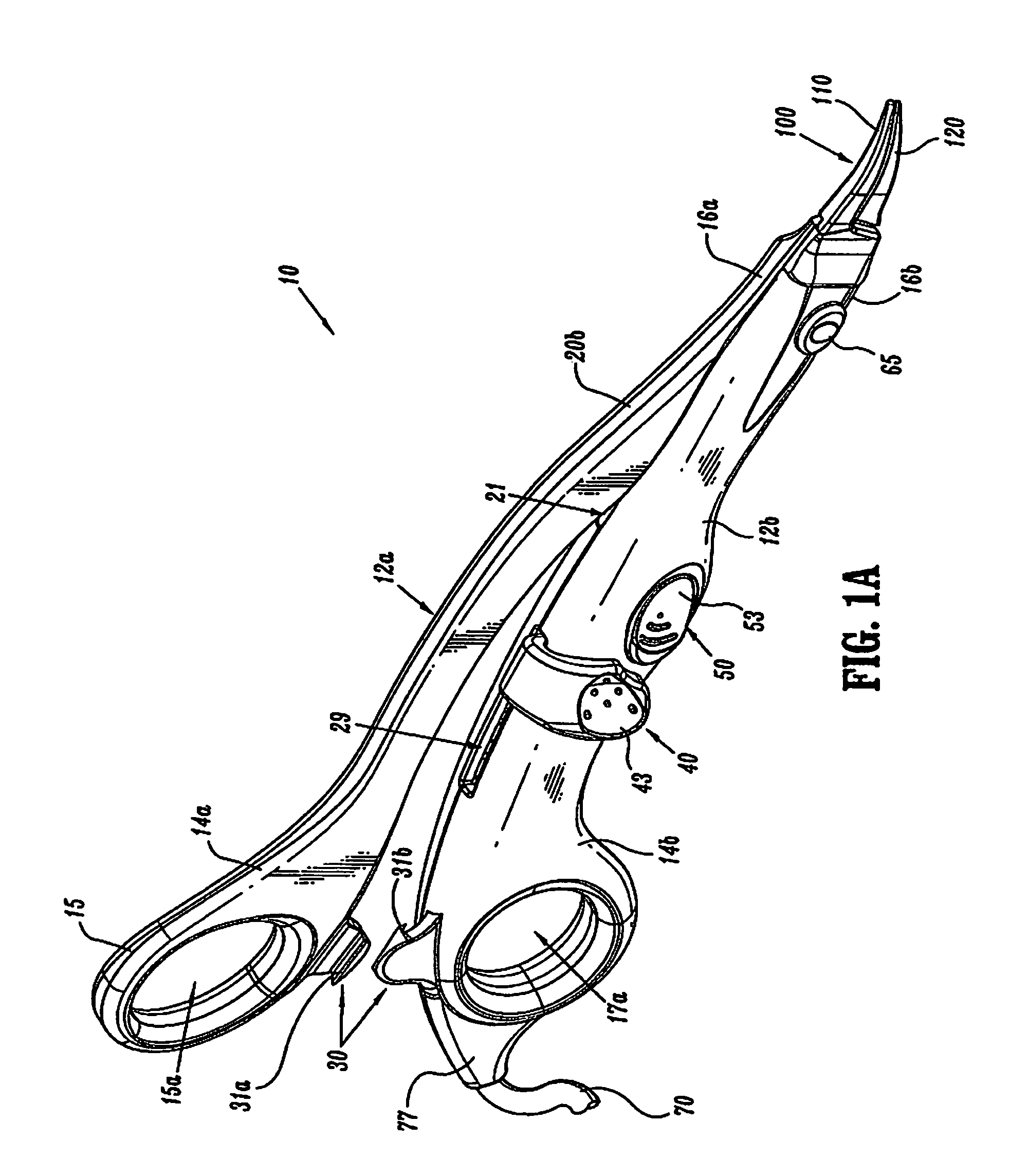
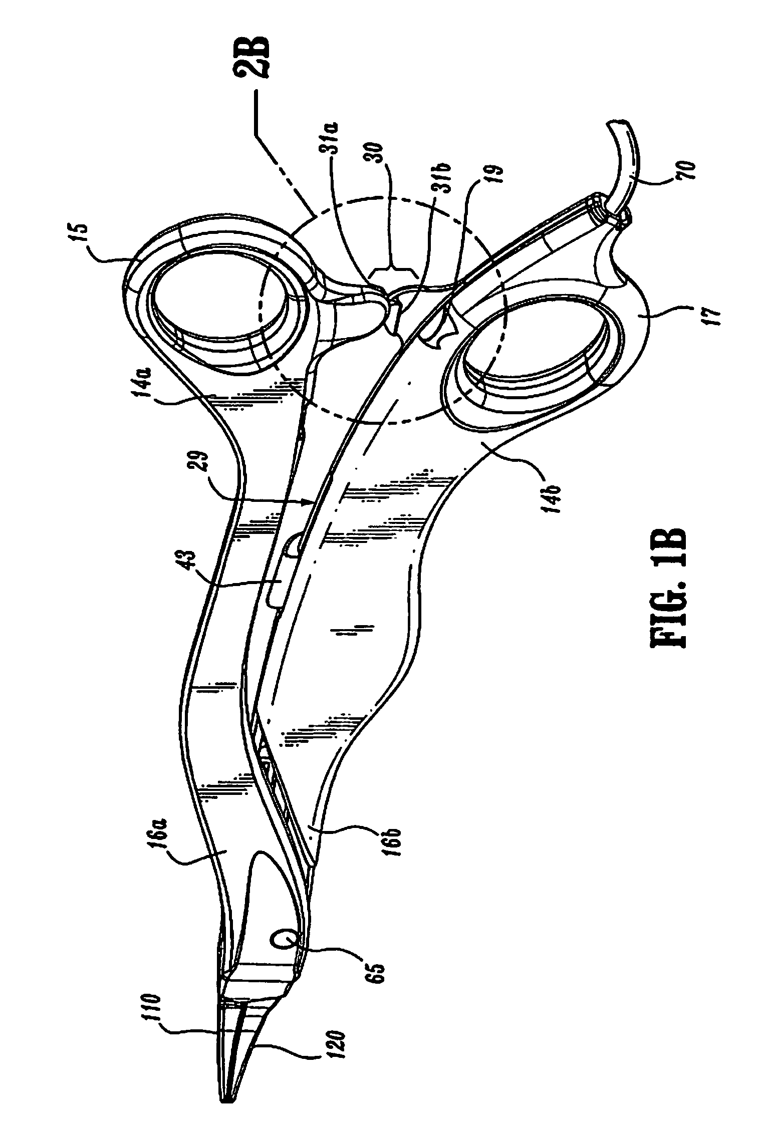
[0049]Referring now to FIGS. 1-7A, a forceps 10 for use with open surgical procedures includes elongated shaft portions 12a and 12b each having a proximal end 14a, 14b and a distal end 16a and 16b, respectively. In the drawings and in the descriptions which follow, the term “proximal”, as is traditional, will refer to the end of the forceps 10 which is closer to the user, while the term “distal” will refer to the end which is further from the user.

[0050]The forceps 10 includes an end effector assembly 100 which attaches to the distal ends 16a and 16b of shafts 12a and 12b, respectively. As explained in more detail below, the end effector assembly 100 includes pair of opposing jaw members 110 and 120 which are pivotably connected about a pivot pin 65 and which are movable relative to one another to grasp tissue.

[0051]Each shaft 12a and 12b includes a handle 15 and 17, respectively, disposed at the proximal end 14a and 14b thereof which each define a finger hole 15a and 17a, respectiv...


PUM


Abstract

An open electrosurgical forceps includes a pair of first and second shaft members each having a jaw member disposed at its distal end. The jaw members are movable from a first position in spaced relation relative to one another to a subsequent position wherein the jaw members cooperate to grasp tissue. Each of the jaw members includes an electrically conductive scaling plate for communicating electrosurgical energy through tissue. A curved knife channel is defined along the length of one of the jaw members and is dimensioned to reciprocate a cutting mechanism. An actuator selectively advances the cutting mechanism from a first position proximal to tissue held between the jaw members to a subsequent position distal to tissue held between the jaw members. The cutting mechanism includes a generally hourglass-shaped flexible blade having a mutually aggregating notch.

Description

CROSS-REFERENCE TO RELATED APPLICATION[0001]The present application is a continuation application, which claims the benefit of priority to U.S. patent application Ser. No. 10 / 962,116 filed on Oct. 8, 2004, now U.S. Pat. No. 7,811,283, which claims the benefit of priority to U.S. Provisional Application Ser. No. 60 / 523,387 filed on Nov. 19, 2003 the entire contents of each of which being incorporated by reference herein.BACKGROUND[0002]1. Technical Field[0003]The present disclosure relates to forceps used for open surgical procedures. More particularly, the present disclosure relates to an open forceps which applies a combination of mechanical clamping pressure and electrosurgical energy to seal tissue and a knife which is selectively advanceable to sever tissue along the tissue seal.[0004]2. Background of Related Art[0005]A forceps is a plier-like instrument which relies on mechanical action between its jaws to grasp, clamp and constrict vessels or tissue. So-called “open forceps” a...

Claims


Application Information

Patent Timeline
Patent Type & Authority Patents(United States)
IPC IPC(8): A61B18/14A61B17/125A61B17/12A61B17/28A61B17/3201A61B18/12A61B18/00
CPCA61B2018/1455A61B2018/1432A61B18/1442A61B17/2812A61B2018/00946A61B17/3211A61B2018/00196A61B2018/00404A61B2018/00619A61B2017/2945A61B2018/00345A61B2018/0063A61B17/285A61B2018/1412A61B17/32A61B2018/00601A61B2018/00922
Inventor MOSES, MICHAEL C.ROMERO, PAUL R.JOHNSON, KRISTIN D.KERR, DUANE E.DYCUS, SEAN T.
Owner COVIDIEN AG
Learn More