Method for the automated control of a solar protection installation

a solar protection installation and automatic control technology, applied in the direction of dynamo-electric machines, building components, structural/machine measurement, etc., can solve the problems of not providing such structures, slats with retroreflecting methods, and difficulty in production, so as to achieve the effect of simplifying the production of slats and maintaining maximum visibility

Inactive Publication Date: 2014-01-07
SOMFY ACTIVITES SA
View PDF13 Cites 15 Cited by
  • Summary
  • Abstract
  • Description
  • Claims
  • Application Information

AI Technical Summary

Benefits of technology

[0016]The object of the invention is to provide a specific slat structure which, within the context of dynamic adjustment, ensures optimum protection, without however excessively darkening the room or while maintaining maximum visibility to the outside. In addition, the invention proposes to simplify the production of slats for retroreflective venetian blinds, in an alternative manner to that of existing slats.

Problems solved by technology

Although the above patents seek to simplify these venetian blinds, their production remains difficult, especially in the case of curved shapes, which are the shapes at rest.
In addition, these documents do not provide such structures, just like the previously mentioned patents, for use in a dynamically tiltable blind.
However, this method of regulation is not necessarily suitable for slats having a retroreflecting effect, although dynamic adjustment of the slats allows better use of the solar protection installation by offering possible manual control and manual and / or automatic adjustment options for all situations.

Method used


Image

  • Method for the automated control of a solar protection installation
  • Method for the automated control of a solar protection installation
  • Method for the automated control of a solar protection installation

Examples


Embodiment Construction

)

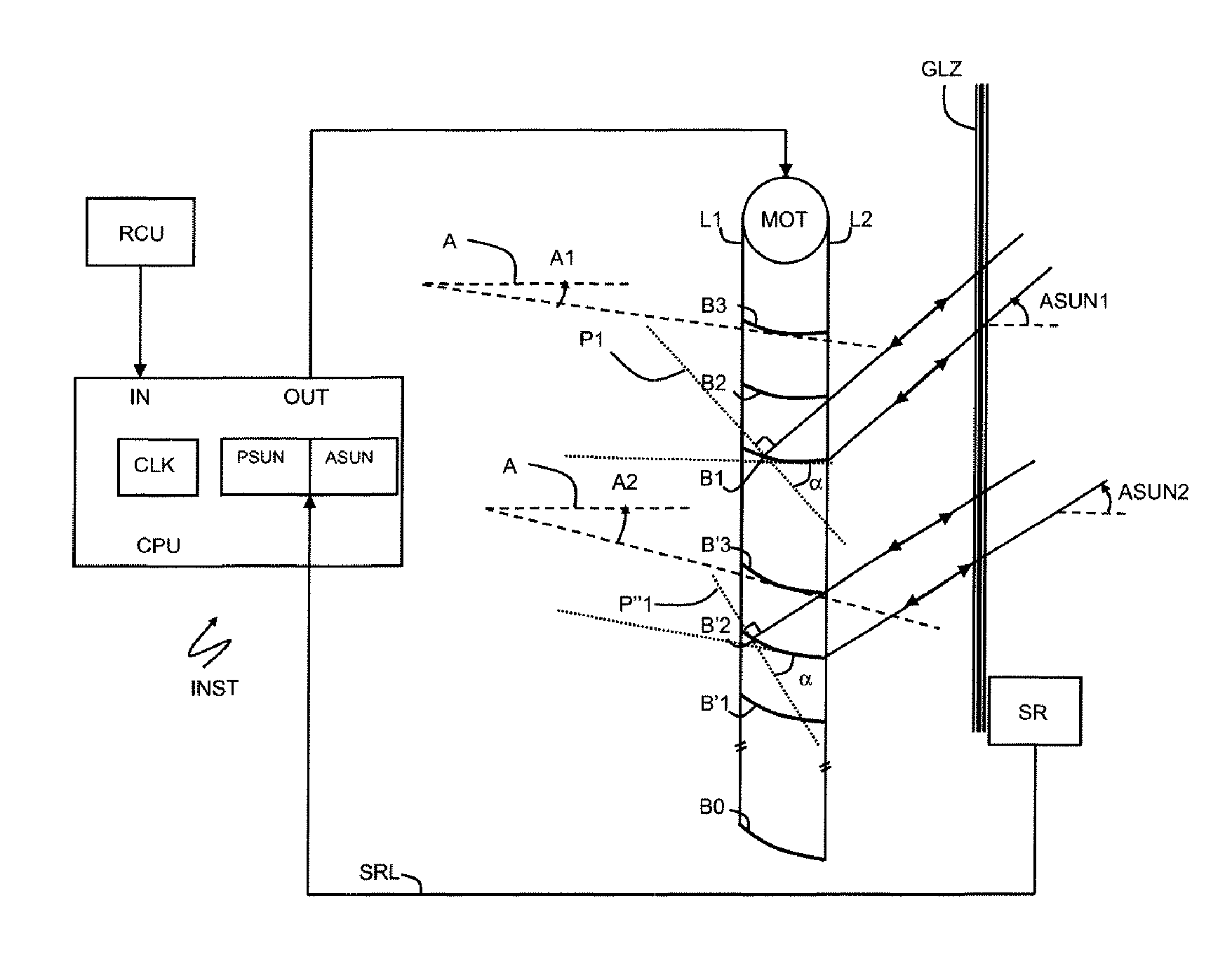
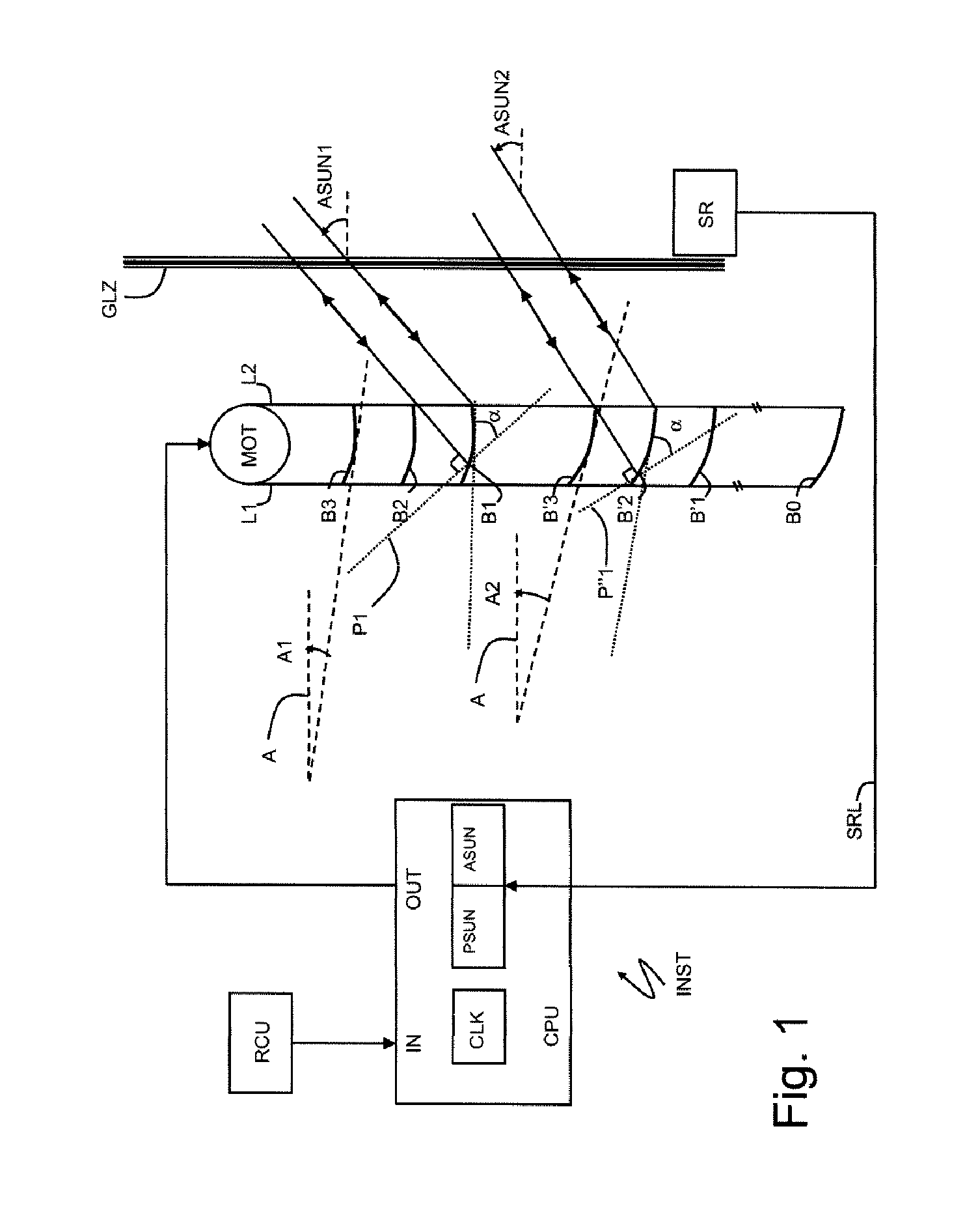
[0025]FIG. 1 shows an installation INST according to the invention. The installation INST comprises a solar protection screen SCR consisting of horizontal slats B1, B2, B3 (or B′1, B′2, B′3) guided for their orientation by ladder strings L1 and L2 that are connected to a motor MOT.

[0026]The screen SCR is placed behind wall façade glazing GLZ, in a room inside a building. Alternatively, the screen is placed in front of the glazing, on the outside of the building.

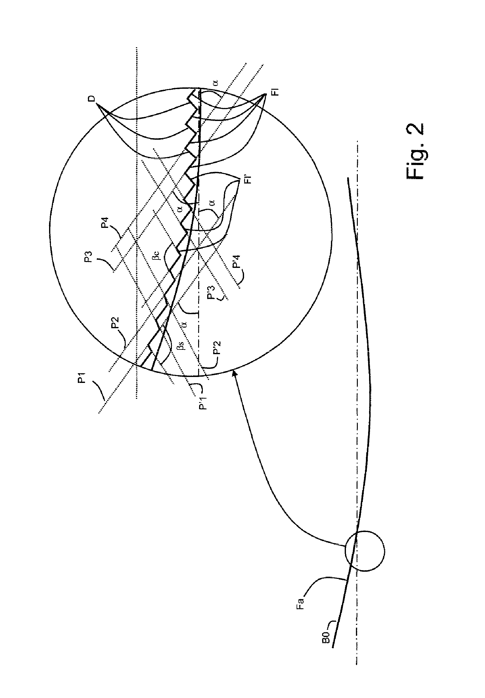
[0027]The slats are of the retroreflective or catadioptric type. Ideally, any ray incident on a slat is reflected in the direction of incidence. The behavior of a slat will be called here retroreflective if this property is verified overall, i.e. if, for at least most of the instant rays and points of incidence, any reflected ray is emitted in a cone of small opening angle (for example 30°) that includes the incident direction. The behavior may be retroreflective only in a certain range of relative angles of inclination of t...


PUM


Abstract

An automated control of a solar protection installation (INST), includes reflecting slats (B1, B2, B3) having parallel longitudinal axes, the slats having a face (F) provided with teeth (D) which flanks (F1), exposable to the light rays and called “useful” flanks, lie in parallel planes (P1, P2, P3, P4). The main direction of incidence (ASUN1; ASUN2) of the light rays on the slats is determined (CPU, CLK, ASUN) and a motor (MOT) is provided for tilting the slats at least substantially about their longitudinal axis. The slats are automatically tilted to orient the planes of the useful flanks depending on the main direction of incidence of the light rays.

Description

[0001]This application is a 371 of PCT / IB2008 / 054781 filed on Nov. 14, 2008 published on May 22, 2009 under publication number WO 2009 / 063428 A and claims priority benefits to French application number 07 08050 filed Nov. 16, 2007, the entire disclosure of which is incorporated herein by reference.BACKGROUND OF THE INVENTION[0002]The invention relates to the field of tiltable solar protection devices, particularly interior venetian blinds, comprising a plurality of horizontal slats arranged parallel to one another and a mechanism for varying the tilting angle of these slats. Conventional venetian blind slats generally have smooth surfaces and a curved section, the latter providing the stiffness necessary for the holding and tilting of the slats (the slats being supported only by ladder strings at their ends).DESCRIPTION OF THE PRIOR ART[0003]There is extensive prior art on various shapes of solar protection devices that are either tiltable or fixed. In the second case, structures fo...

Claims


Application Information

Patent Timeline
Patent Type & Authority Patents(United States)
IPC IPC(8): F04D15/00E06B9/30G05D23/00E06B9/00G08B13/08
CPCE06B9/32E06B9/386
Inventor NEUMAN, SERGE
Owner SOMFY ACTIVITES SA
Why Eureka
Try Eureka