

High-lift device track having a U-shaped to H-shaped cross-section
a technology of high-lift device and cross-section, which is applied in the direction of wing adjustment, wing, transportation and packaging, etc., can solve the problems of assembly principles and quality assurance procedures, complex and time-consuming, and limitations at different manufacturing operations, so as to simplify the manufacturing and assembly of the high-lift device track, the effect of reducing deformation
- Summary
- Abstract
- Description
- Claims
- Application Information
AI Technical Summary
Benefits of technology
Problems solved by technology
Method used
Image

Examples
Embodiment Construction
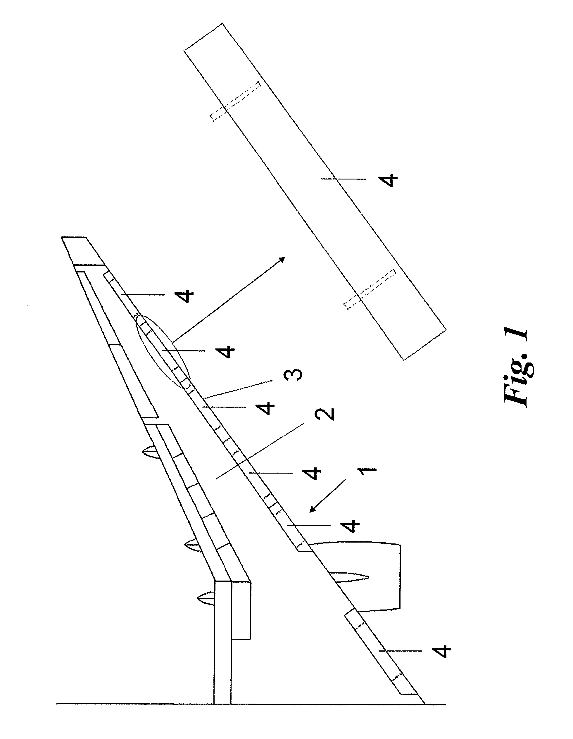
[0034]An airfoil, in the form of an aircraft wing 1, is shown on FIG. 1. This aircraft wing 1 comprises a main body 2 as well as, at its leading edge 3, a set of moveable high-lift devices in the form of slats 4. These slats 4 are moveable between a retracted position in which they sit flush with the main body 2 as shown, and an extended position (not illustrated), in which they are spaced forward with respect to the main body 2. Each of these slats 4 is supported, guided and driven through their movement by a plurality of tracks 5.
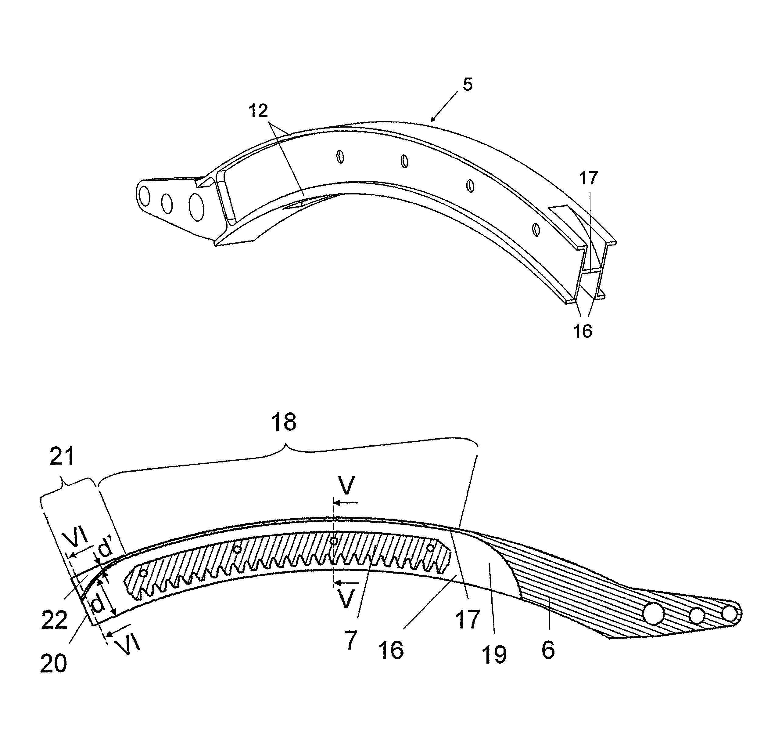
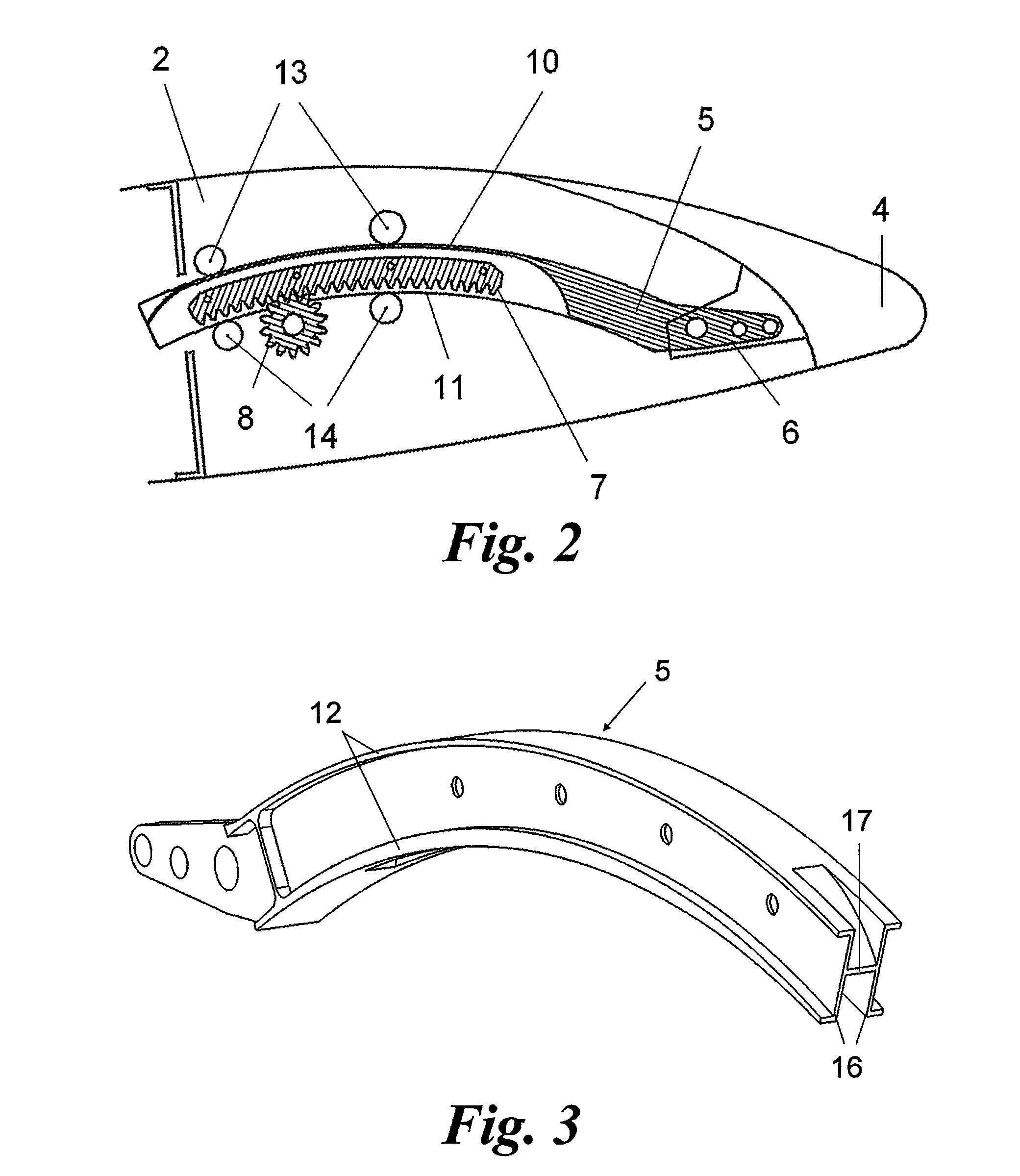
[0035]FIG. 2 shows the high-lift device assembly comprising one such slat 4 as well as one of the tracks 5 attached to it. In the illustrated embodiment, this track 5 is curved so as to guide the slat 4 along a curved trajectory during its extension and retraction. Each track 5 comprises a first track end 6 with attachment points for the slat 4, a gear rack 7 in engagement with an output pinion 8 of a rotational actuator (not illustrated), an upper racewa...
PUM
| Property | Measurement | Unit |
|---|---|---|
| depth | aaaaa | aaaaa |
| area | aaaaa | aaaaa |
| durability | aaaaa | aaaaa |
Abstract
Description
Claims
Application Information