High-Lift Device Track

a high-lift device and track technology, applied in the direction of aircraft components, wing adjustments, aircraft control, etc., can solve the problems of assembly principles and quality assurance procedures, complex and time-consuming, and cost, and achieve the effect of simplifying the manufacturing and assembly of the high-lift device track and reducing deformations

Active Publication Date: 2011-05-05
ASCO IND NV
View PDF19 Cites 7 Cited by
  • Summary
  • Abstract
  • Description
  • Claims
  • Application Information

AI Technical Summary

Benefits of technology

[0008]It is an object of the present invention to simplify the manufacturing and assembly of the high-lift device track by reducing the deformations caused by the release

Problems solved by technology

This can lead to complex and time consuming, thus costly, assembly principles and quality assurance

Method used


Image

  • High-Lift Device Track
  • High-Lift Device Track
  • High-Lift Device Track

Examples


Embodiment Construction

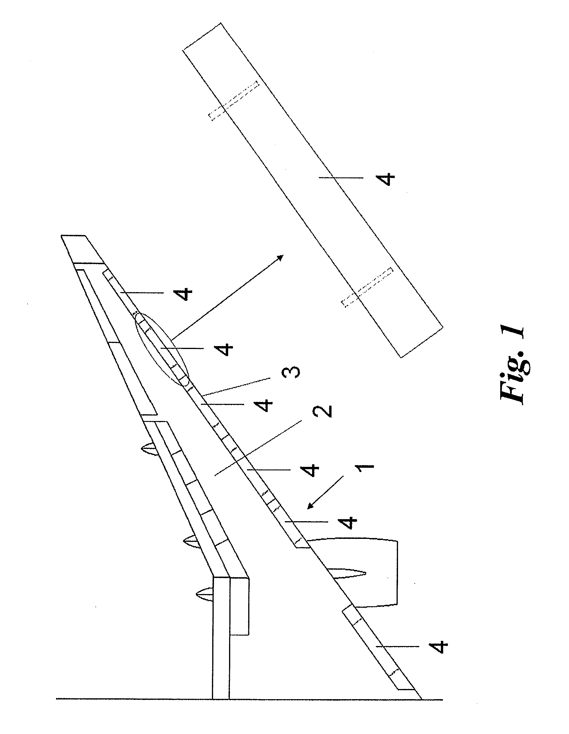
[0034]An airfoil, in the form of an aircraft wing 1, is shown on FIG. 1. This aircraft wing 1 comprises a main body 2 as well as, at its leading edge 3, a set of moveable high-lift devices in the form of slats 4. These slats 4 are moveable between a retracted position in which they sit flush with the main body 2 as shown, and an extended position (not illustrated), in which they are spaced forward with respect to the main body 2. Each of these slats 4 is supported, guided and driven through their movement by a plurality of tracks 5.

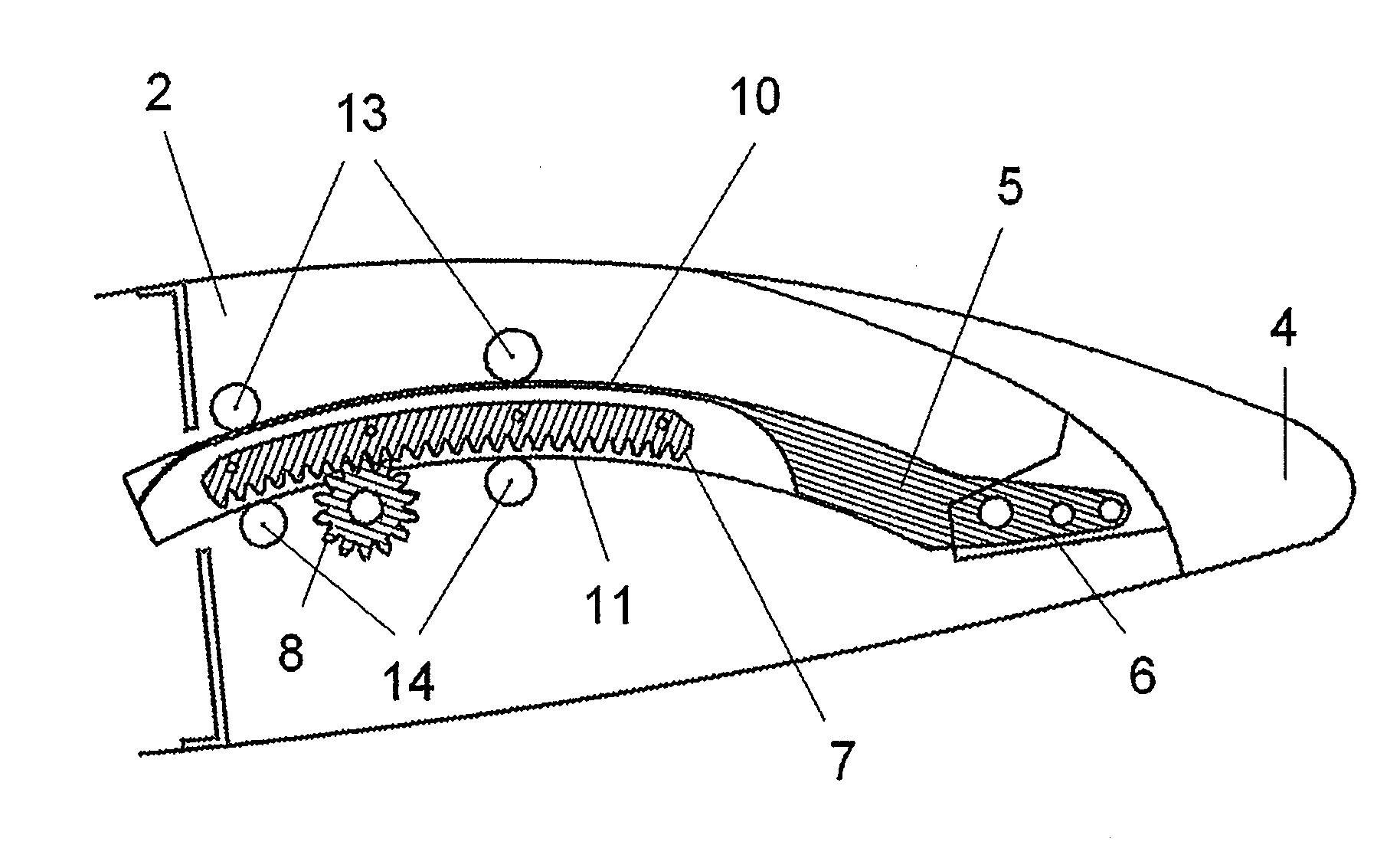
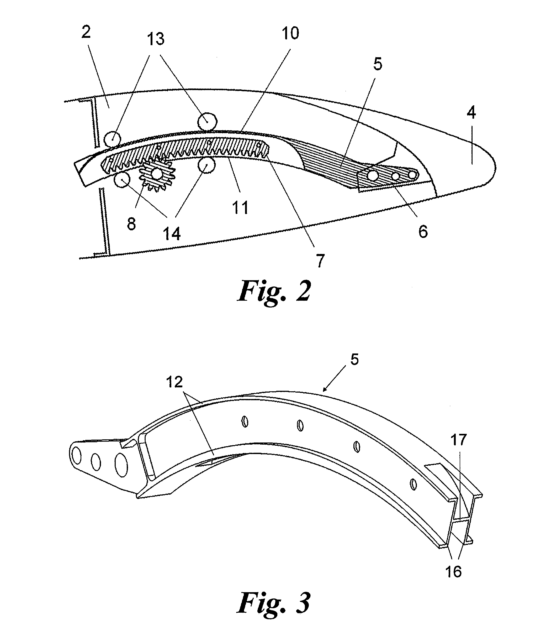
[0035]FIG. 2 shows the high-lift device assembly comprising one such slat 4 as well as one of the tracks 5 attached to it. In the illustrated embodiment, this track 5 is curved so as to guide the slat 4 along a curved trajectory during its extension and retraction. Each track 5 comprises a first track end 6 with attachment points for the slat 4, a gear rack 7 in engagement with an output pinion 8 of a rotational actuator (not illustrated), an upper racewa...


PUM

PropertyMeasurementUnit
Depthaaaaaaaaaa

Abstract

The present invention relates to a high-lift device track 5 comprising a first track end 6 comprising attachment points for the high-lift device 4, two vertical flanges 16 connected by a horizontal web 17, a set of raceways 10,11,12 for guiding rollers 13 or glide pads, and a gear rack 7 installed between said flanges 16 over a first track segment 18. This first track segment 18 presents an inverted-U, or cross-section. However, between said first track segment 18 and a second track end 20 opposite to said first track end 6, the track 5 comprises a second track segment 21 presenting a depth d between the horizontal web 17 and lower edges 25 of the vertical flanges 16 which decreases towards said second track end 20, so that, at said second track end, the track presents an H cross-section.

Description

TECHNICAL FIELD[0001]The present invention relates to tracks for the support and deployment of high-lift devices in airfoils, and in particular to slat tracks.[0002]To temporarily increase the lift generated by airfoils, in particular aircraft wings, it is well-known in the art to deploy movable high-lift devices, such as leading edge slats or trailing edge flaps, from a retracted position to an extended position in which they increase the area and / or camber of the airfoil. In the case of leading edge slats, their deployment may also create at least one opening between the slat and the main body of the airfoil.BACKGROUND OF THE INVENTION[0003]To support such high-lift devices and guide them during their deployment, it is also well-known in the art to use tracks fixed to the high-lift device and comprising raceways for contacting rollers or glide pads mounted on the main body of the airfoil.[0004]Besides support and guidance of the movable high-lift devices, transferring aerodynamic ...

Claims


Application Information

Patent Timeline
IPC IPC(8): B64C3/50B23P17/00
CPCY10T29/49622B64C9/22
Inventor LAUWEREYS, GUYPAULIS, FREDERICRAMIREZ GARCIA, MIGUELRAMIREZ RAMIREZ, JUAN-CARLOSVANDEGAER, STIJNVANDENBULCKE, YVON
Owner ASCO IND NV
Why Eureka
Try Eureka