Engine Balance System

a technology of engine balance and balance plate, which is applied in the direction of machines/engines, shafts, bearings, etc., can solve the problems of reducing the useful life of machines, causing operator fatigue, and single cylinder engines to be piston reciprocating, so as to reduce the weight and vibration, reduce the undesirable rotational movement of the counterweight, and improve the performance

Active Publication Date: 2009-09-17
KOHLER CO
View PDF15 Cites 1 Cited by
  • Summary
  • Abstract
  • Description
  • Claims
  • Application Information

AI Technical Summary

Benefits of technology

[0009]The present inventors have recognized the above-described disadvantages associated with many conventional balance system designs. The present inventors have additionally recognized that improved performance can be achieved by a balance system if, in at least some embodiments, a counterweight of the balance system that is intended for movement back and forth with respect to the crankshaft is coupled to an inner wall of a crankcase not merely by way of a single hinged arm, but rather is coupled to an inner wall of the crankcase by way of a pair of hinged arms rotatably coupled respectivel

Problems solved by technology

A major cause of vibration in a single cylinder engine is piston reciprocation.
This vibration is uncomfortable and could produce operator fatigue.
Even when operated in a device in which there is no issue of operator fatigue (e.g., sump pumps or portable generators), engine vibration is undesirable because it causes maintenance problems and tends to reduce the useful life of the machine.
However, the centrifugal force of such rotating crankshaft counterweights also has a component transverse to the piston axis that produces lateral vibration, the amount of which increases in direction proportion to the degree to which the crankshaft counterweights successfully cancel out the acceleration and deceleration forces on the piston assembly.
Yet the use of such counterweights having a 50% overbalance condition does not fully eliminate the undesirable vibration occurring in single cylinder engines.
While the above-described conventional design for a balance system successfully balances to a high degree the f

Method used


Image

  • Engine Balance System
  • Engine Balance System
  • Engine Balance System

Examples


Embodiment Construction

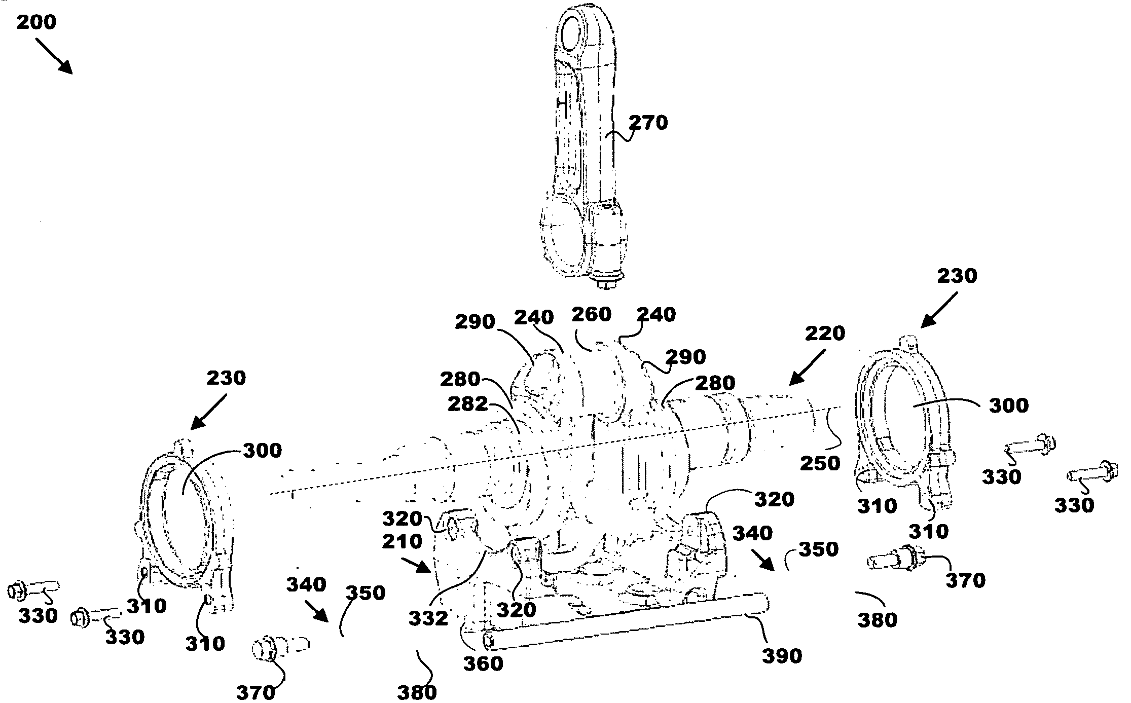
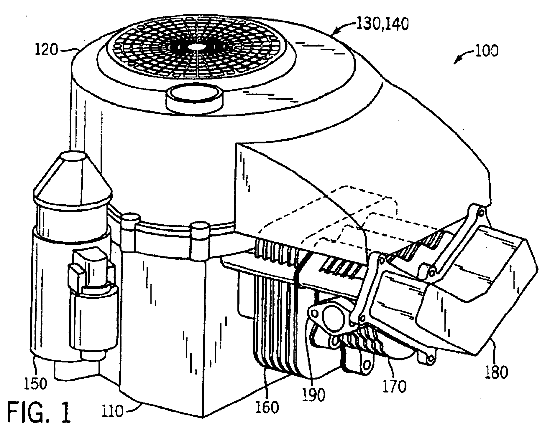
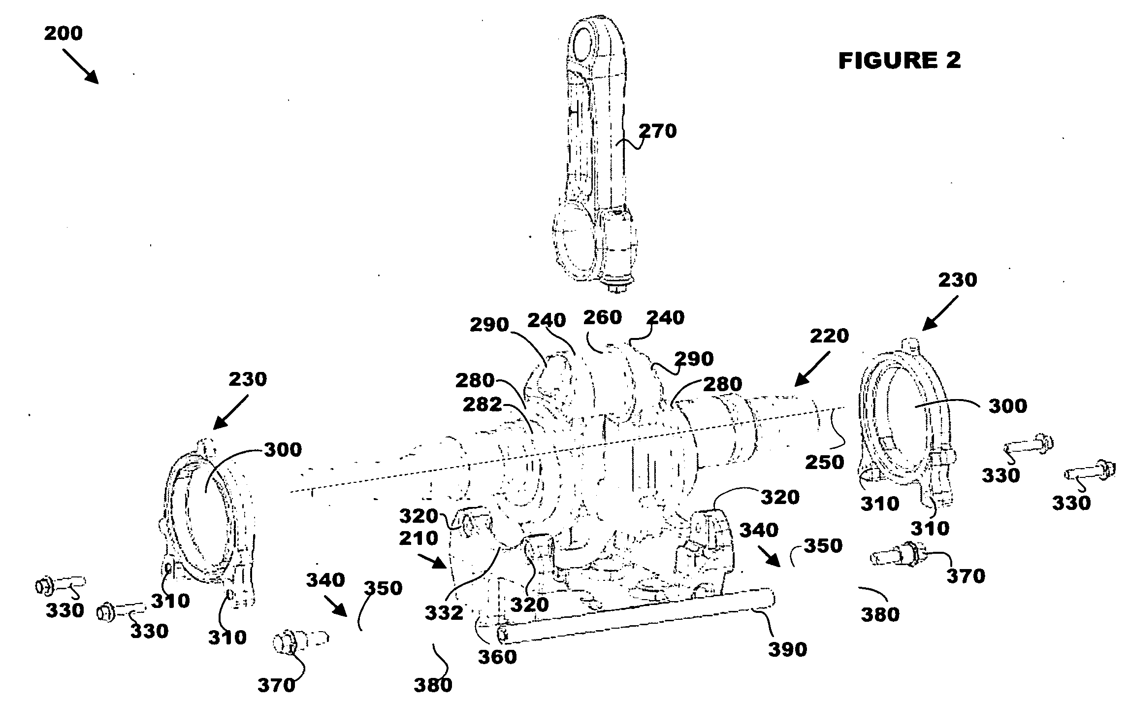
[0017]Referring to FIG. 1, a single cylinder, 4-stroke, internal combustion engine 100 designed by Kohler Co. of Kohler, Wis. includes a crankcase 110 and a blower housing 120, inside of which are a fan 130 and a flywheel 140. The engine 100 further includes a starter 150, a cylinder 160, a cylinder head 170, and a rocker arm cover 180. Attached to the cylinder head 170 is an air exhaust port 190. During operation of the engine 100, a piston (not shown) moves back and forth in a linear manner (that is, reciprocates) within the cylinder 160 towards and away from the cylinder head 170. The movement of the piston in turn causes rotation of a crankshaft 220 (see FIG. 2), as well as rotation of the fan 130 and the flywheel 140, which are coupled to the crankshaft. The rotation of the fan 130 cools the engine, and the rotation of the flywheel 140 causes a relatively constant rotational momentum to be maintained. As will be described below in relation to FIGS. 2 and 3, the engine 100 furth...


PUM


Abstract

A balance system for implementation within an engine crankcase, as well as an engine employing such a system and a method of balancing forces as performed by such a system, are disclosed. In at least one embodiment, the balance system includes a crankshaft with at least one eccentric portion and a counterbalance assembly having at least one connecting arm and a counterbalance weight with first and second ends, where each of the at least one connecting arm includes a respective circular orifice that is positioned around and supported by a respective one of the at least one eccentric portion. The balance system further includes first and second hinged arms rotatably coupled proximate the first and second ends of the counterbalance weight, respectively, where the arms at least indirectly link the ends of the counterbalance weight to a portion of the engine crankcase and guide movement of the counterbalance weight.

Description

CROSS-REFERENCE TO RELATED APPLICATIONS[0001]This application claims the benefit of U.S. Provisional Patent Application No. 61 / 035,677 entitled “Engine Balance System” filed on Mar. 11, 2008, which is hereby incorporated by reference herein.STATEMENT REGARDING FEDERALLY SPONSORED RESEARCH OR DEVELOPMENTFIELD OF THE INVENTION[0002]The present invention relates to single cylinder internal combustion engines such as those used to power lawnmowers, sump pumps, portable generators and other devices. In particular, the present invention relates to a balance system within such an engine that nullifies or reduces vibration of the engine resulting from reciprocation of the piston within the engine.BACKGROUND OF THE INVENTION[0003]A major cause of vibration in a single cylinder engine is piston reciprocation. The piston is started and stopped twice during each rotation of the crankshaft, and reactions to the forces that accelerate and decelerate the piston are imposed upon the engine body as ...

Claims


Application Information

Patent Timeline
IPC IPC(8): F02B75/06
CPCF16F15/26F02B75/06F16C3/20
Inventor SMIES, MICHAEL E.UEBELHER, EDWARD A.
Owner KOHLER CO
Why Eureka
Try Eureka