Bearing structure of turbocharger

a technology of bearing structure and turbocharger, which is applied in the direction of positive displacement liquid engines, piston pumps, machines/engines, etc., can solve the problems of excessive outflow of lubricant oil to the outside of the bearing along the oil groove, the seizure of the rotor shaft, and the increase in the amount of supplied oil, so as to suppress the excessive outflow of lubricant oil, reduce the speed of oil film, and suppress the effect of whirl vibration

Inactive Publication Date: 2014-01-14
TOYOTA IND CORP
View PDF17 Cites 28 Cited by
  • Summary
  • Abstract
  • Description
  • Claims
  • Application Information

AI Technical Summary

Benefits of technology

[0006]It can be contemplated that oil grooves are formed throughout the entire length in the axial direction of each inside surface of the first and second bearing portions, so as to reduce the whirl speed of oil film and thereby suppress the whirl vibration. However, in the case where the oil grooves are formed throughout the entire length in the axial direction of each inside surface of the first and second bearing portions, the whirl vibration can be suppressed, but the lubricant oil supplied into the oil passage of the bearing member becomes more likely to outflow excessively to the outside of the bearing along the oil grooves. For this reason, the excessive outflow of lubricant oil leads to increase in amount of supplied oil and possibly leads to degradation of oil seal performance.
[0007]An object of the present invention is therefore to provide a bearing structure of a turbocharger capable of suppressing the whirl vibration of the rotor shaft due to the oil film formed in the space between each inside surface of the first and second bearing portions of the bearing member and the rotor shaft and also capable of suppressing the excessive outflow of lubricant oil.
[0009]In the present invention, the whirl speed of oil film is reduced and the whirl vibration is suppressed by the oil grooves formed in the respective inside surfaces of the first and second bearing portions of the bearing member. The oil grooves are closed in part, thereby to suppress the excessive outflow of lubricant oil.
[0010]The oil grooves may be open on the oil passage side and closed on end sides of the bearing member. When the oil grooves are those open on the oil groove side and closed on the end sides of the bearing member, the lubricant oil is smoothly supplied to the space between each inside surface of the first and second bearing portions and the outer periphery of the rotor shaft to form oil film. This prevents the seizure and suppresses the whirl vibration.

Problems solved by technology

However, there is concern about seizure of the rotor shaft due to film disruption.
However, in the case where the oil grooves are formed throughout the entire length in the axial direction of each inside surface of the first and second bearing portions, the whirl vibration can be suppressed, but the lubricant oil supplied into the oil passage of the bearing member becomes more likely to outflow excessively to the outside of the bearing along the oil grooves.
For this reason, the excessive outflow of lubricant oil leads to increase in amount of supplied oil and possibly leads to degradation of oil seal performance.

Method used


Image

  • Bearing structure of turbocharger
  • Bearing structure of turbocharger
  • Bearing structure of turbocharger

Examples


Embodiment Construction

[0019]The preferred embodiments of the present invention will be described below in detail with reference to the accompanying drawings. In the description the same elements or elements with the same functionality will be denoted by the same reference signs, without redundant description.

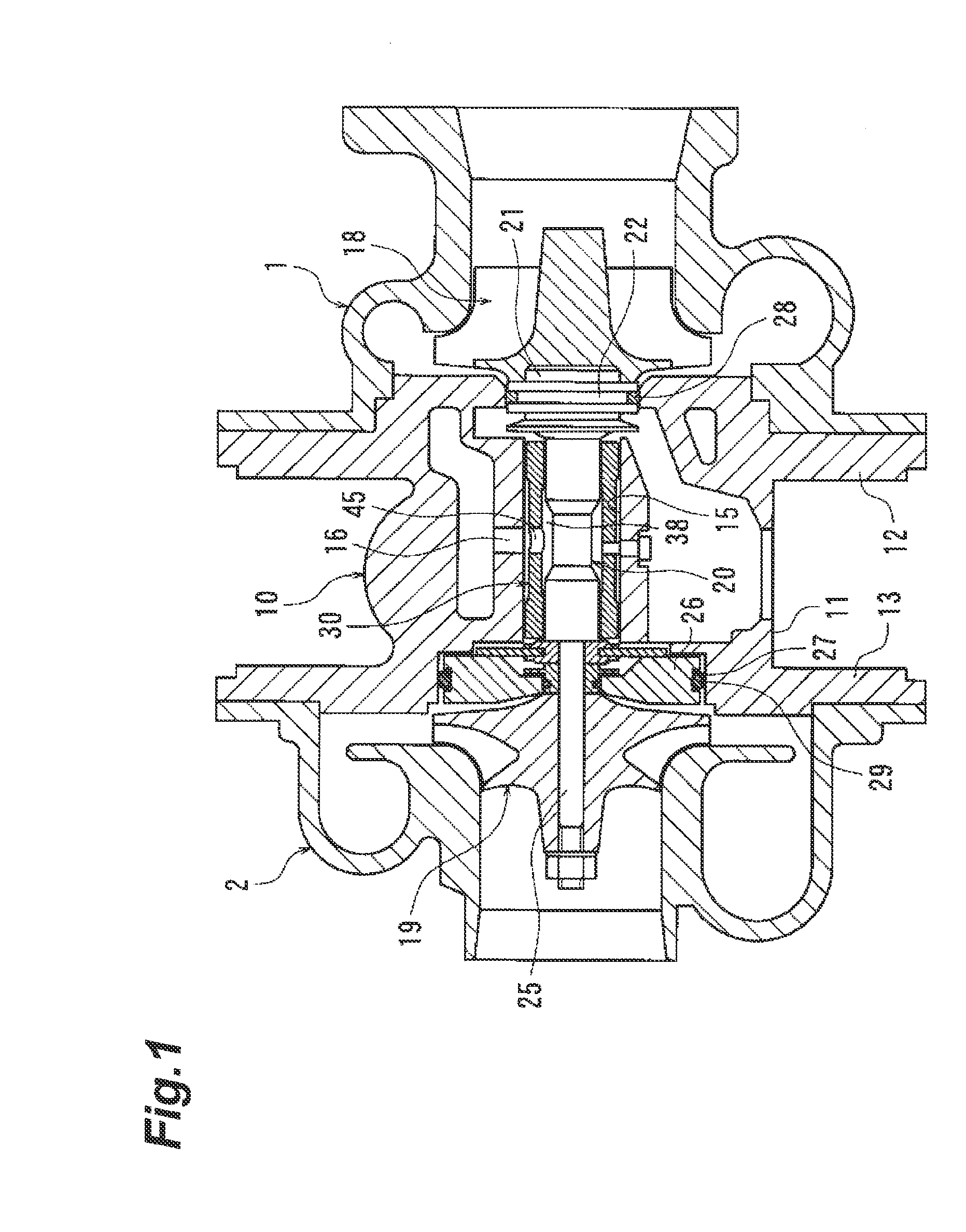
[0020]A bearing structure of a turbocharger according to an embodiment of the present invention will be described with reference to FIGS. 1 to 4. As shown in FIG. 1, the turbocharger is provided with a turbine housing 1, a compressor housing 2, a bearing housing 10, a turbine wheel 18, a compressor impeller 19, and a rotor shaft 20.

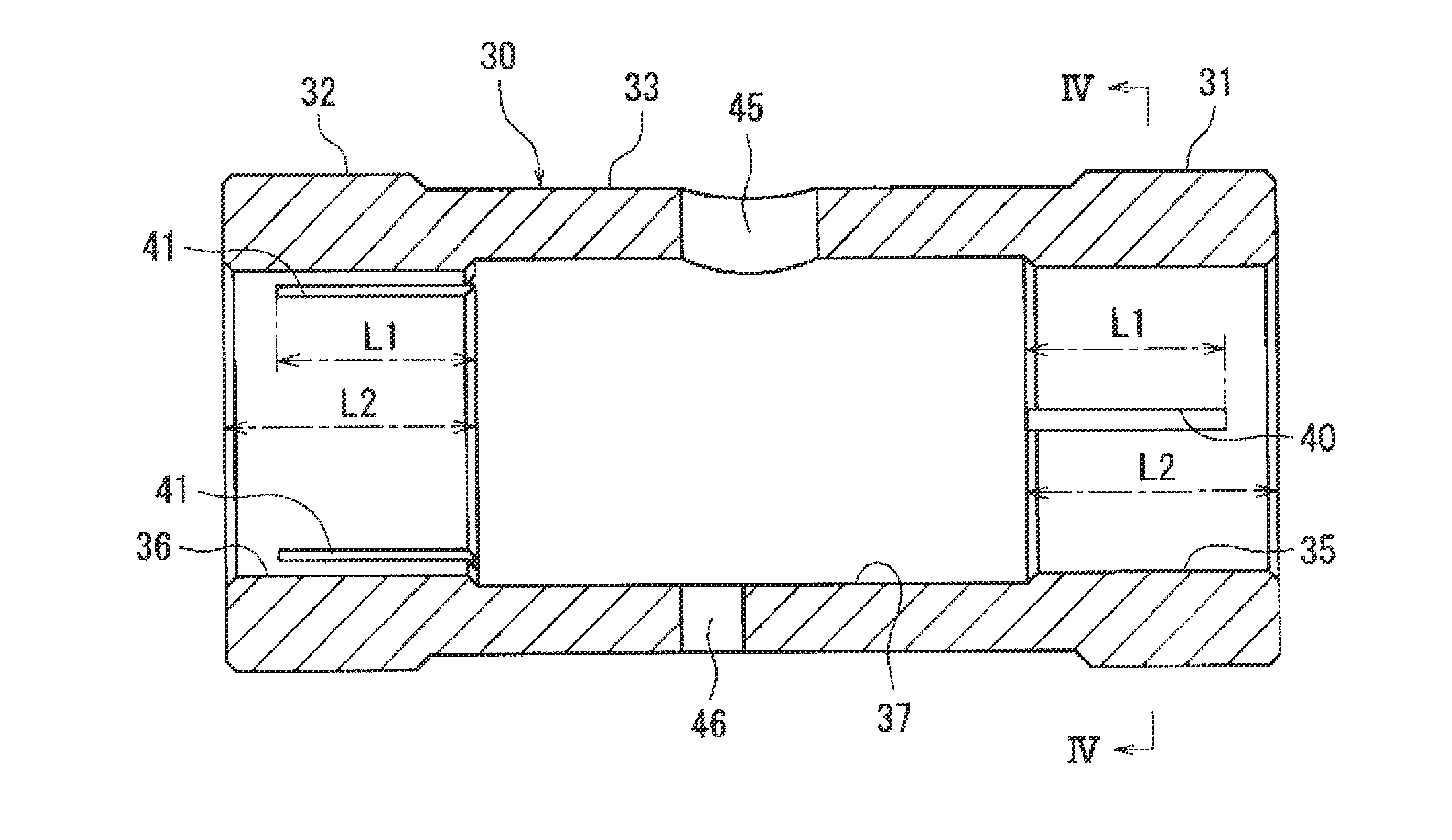
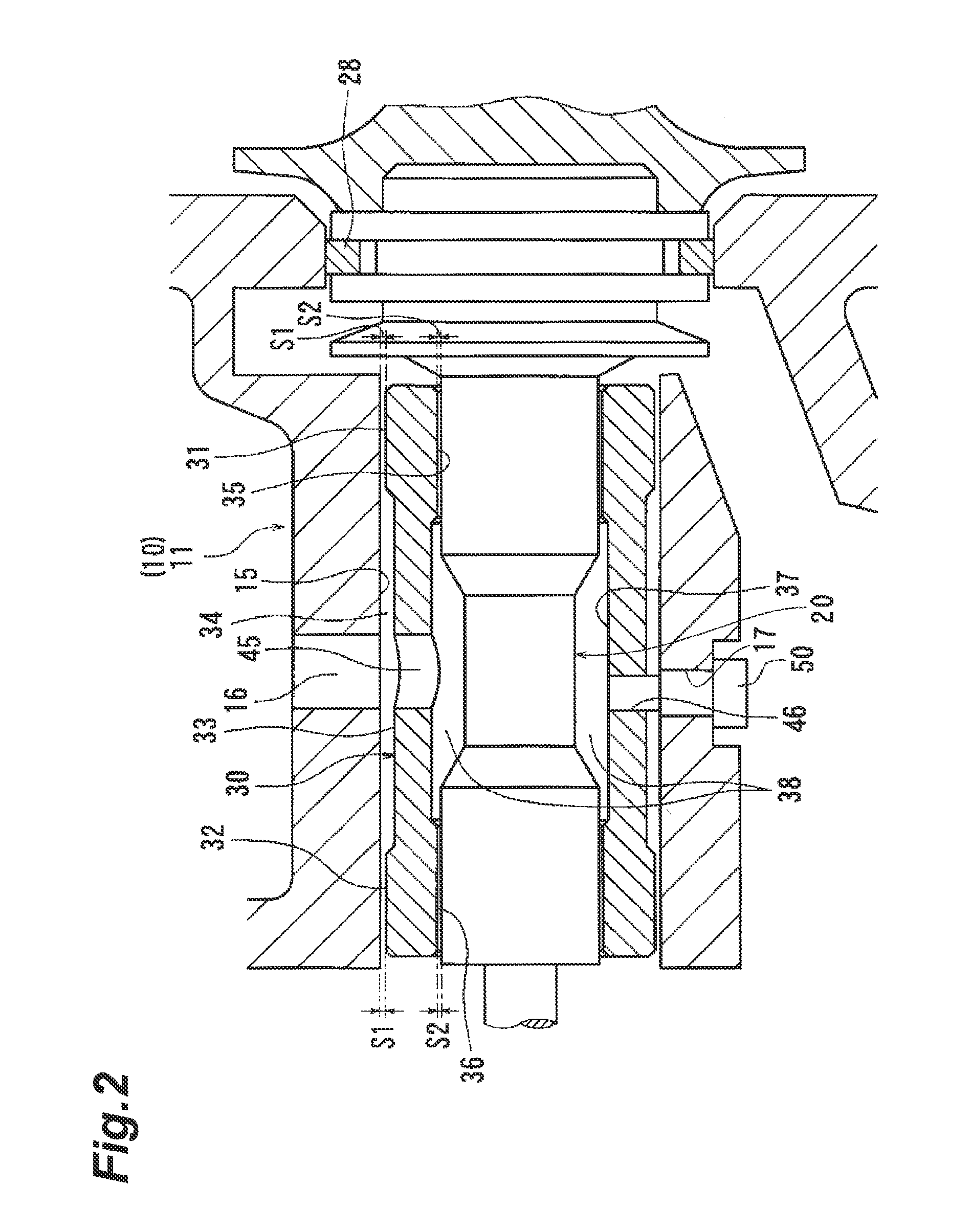
[0021]The bearing housing 10 has a housing body 11 through a central region of which a bearing hole 15 is formed, a turbine-side flange 12 arranged around the outer periphery at one end of the housing body 11, and a compressor-side flange 13 arranged around the outer periphery at the other end of the housing body 11. The rotor shaft 20 is rotatably incorporated through a b...


PUM


Abstract

A turbocharger is provided with a rotor shaft, a bearing housing in which a bearing hole is formed, and a bearing member of the semi-floating type arranged in the bearing hole and supporting the rotor shaft in a rotatable state. The bearing member has a first bearing portion and a second bearing portion spaced at a predetermined interval in the axial direction of the rotor shaft, in its inner periphery. A region between the first bearing portion and the second bearing portion in the inner periphery of the bearing member, and an outer periphery of the rotor shaft constitute an oil passage for supply of lubricant oil to inside surfaces of the first and second bearing portions. Oil grooves to suppress the whirl vibration are formed in each of the inside surfaces of the first and second bearing portions. The oil grooves are closed in part.

Description

BACKGROUND OF THE INVENTION[0001]1. Field of the Invention[0002]The present invention relates to a bearing structure of a turbocharger.[0003]2. Related Background Art[0004]Japanese Patent Applications Laid-open No. 2007-170296 and Laid-open No. 2010-138757 disclose turbocharger bearing structures provided with a rotor shaft, a bearing housing in which a bearing hole is formed, and a bearing member of the semi-floating type arranged in the bearing hole and supporting the rotor shaft in a rotatable state. In the turbocharger bearing structures described above, the bearing member has a first bearing portion and a second bearing portion spaced at a predetermined interval in the axial direction of the rotor shaft, in its inner periphery. The region between the first bearing portion and the second bearing portion in the inner periphery of the bearing member and the outer periphery of the rotor shaft constitute an oil passage for supply of lubricant oil to inside surfaces of the first and ...

Claims


Application Information

Patent Timeline
Patent Type & Authority Patents(United States)
IPC IPC(8): F04B17/00F16C33/10
CPCF01D25/18F01D25/166F05D2220/40F16C17/18F16C2360/24F16C33/1065F16C27/02F16C17/02F16C2226/50F16C2240/42
Inventor UESUGI, TSUYOSHI
Owner TOYOTA IND CORP
Why Eureka
Try Eureka