
Multi-bladed expandable broadhead

a multi-blade, expandable technology, applied in the field of archery, can solve the problems of unintended arrow path away from the aimed path to the vital organs for a quick kill

Active Publication Date: 2014-01-14
TOG IP LLC
View PDF14 Cites 3 Cited by
  • Summary
  • Abstract
  • Description
  • Claims
  • Application Information

AI Technical Summary

Benefits of technology

The present invention is a mechanical broadhead with a unique design that solves problems with current broadheads. The blade cutting edges are positioned in a way that allows the ferrule tip to contact the animal and direct the head along its intended path. The blade cutting edges are angled relative to the ferrule, allowing for a shorter pivoting rotation to a completely open position and ensuring a maximum entry cut with greater leverage upon contact with an animal. The blade geometry and position also guarantees the blades will always open and produce a killing cut, regardless of regulations. The blades are of a blocky triangular geometry, resulting in greater strength compared to long slender blades. The distance between the pivot and the nearest point on the cutting edge is at least as long as the distance from the point to a distal end of the blade, and a generally triangular web between the cutting edge and the pivot further strengthens the blade and insures the blade can be pulled out without any barb structure behind the cutting edge. The distance between the distal ends of the main cutting edges in closed flight position is between 1.0 and 1.5 times the distance in closed flight position, and in some preferred embodiments, the maximum spread of the blades is also 1.1 to 1.5 times the closed spread between the distal ends of the cutting edges. The mechanical broadhead of the present invention has excellent flight characteristics and great effectiveness as a hunting head.

Problems solved by technology

The inventor has observed that the farther forward the blade tips are positioned and the more parallel the blade edge angle and blade tip is to the ferrule, the greater the undesirable “pole vaulting” effect of pushing the ferrule tip off course upon entry when the blade tips contact bone, resulting in an unintended arrow path away from the aimed path to the vital organs for a quick kill.

Method used


Image

  • Multi-bladed expandable broadhead
  • Multi-bladed expandable broadhead
  • Multi-bladed expandable broadhead

Examples


Embodiment Construction

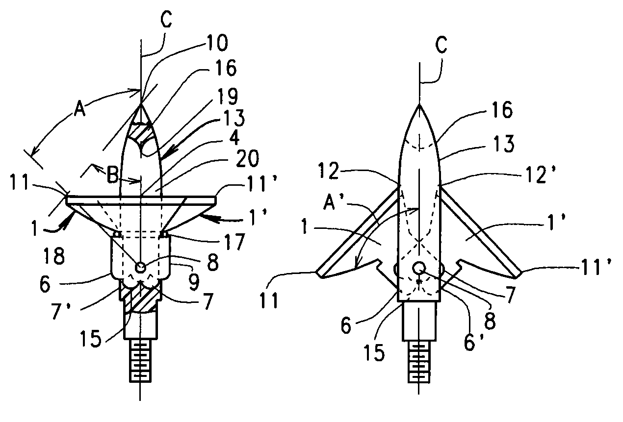
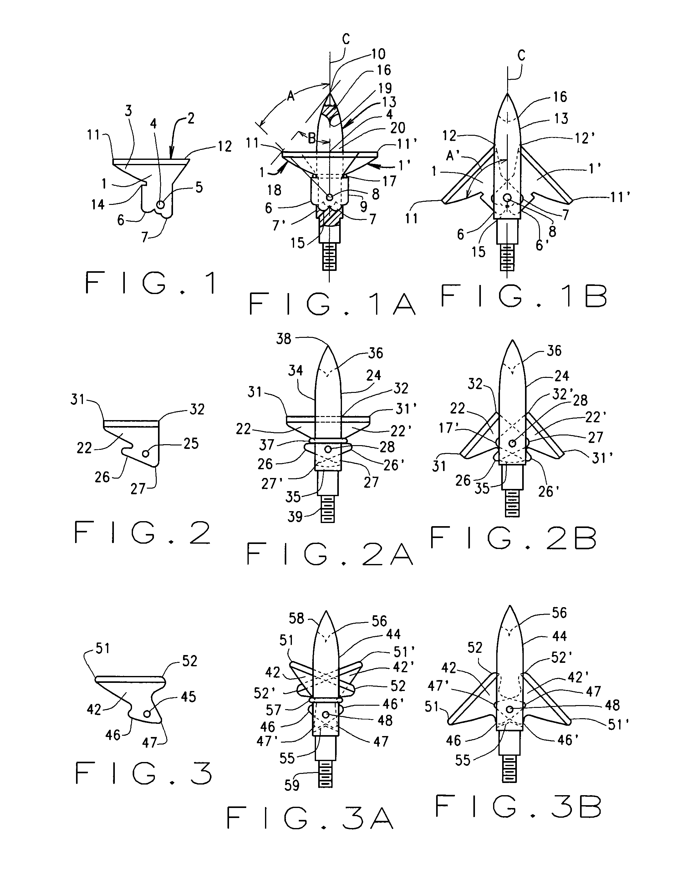
[0049]Referring to FIG. 1, arrowhead blade 1 of the present invention includes a forwardly-facing sharpened main cutting edge 2, a generally triangular web portion 3 behind the edge 2, a pivot hole 5, rotation-limiting base portions 6 and 7, and a notch 14. Because the sharpened cutting edge 2 of this embodiment is a straight line, the closest point 4 on the edge to the pivot hole 5 is the intersection with the cutting edge of a line perpendicular to it through the hole 5. The main cutting edge 2 has distal end 11 in relation to pivot hole 5 and proximal end 12 in relation to pivot hole 5. The cutting edge 2 of blade 1 is about 1.2″ long, about 0.7″ from the point 4 to the distal end 11 and about 0.5″ from the point 4 to proximal end 12. The distance from the center of hole 5 to the point 4 is about 0.7″.

[0050]FIG. 1A depicts an arrowhead of the present invention in a closed flight position. The arrowhead includes a body or ferrule 13 having a threaded arrow-engaging rear ferrule en...


PUM


Abstract

An aerodynamic multi-bladed expandable broadhead with rearward mounted overlapping blades with greater in-flight blade angles along with substantially perpendicular blade edges relative to the arrowhead body. Position of blades in flight guarantees they will always make a lethal cut on contact with an animal even before expansion. Greater in-flight blade angle means less force to open blades on hide guaranteeing expansion, and minimal rotation of blades to the penetration position results in a maximum entry cut and greater penetration. By expanding the distance between the blade edge and pivot a stronger blocky blade is produced. Geometry dictates during entry when blades hit bone on angle shots arrow direction will favorably remain in its intended lethal path to an animal.

Description

CROSS-REFERENCE TO RELATED APPLICATIONS[0001]This application is a continuation-in-part of U.S. application Ser. No. 12 / 961,306, filed Dec. 6, 2010, now U.S. Pat. No. 8,272,979, issued Sep. 25, 2012, which claims the benefit of U.S. Provisional application Ser. No. 61 / 266,585, filed Dec. 4, 2009. Both these applications are incorporated herein by reference.BACKGROUND OF THE INVENTION[0002]The present invention relates to the field of archery, more specifically to hunting arrowheads called broadheads. There are two types of broadheads: fixed where there are no moving parts and a constant cutting diameter, and mechanical where there are moving parts. Mechanical broadheads have less surface area in flight for great accuracy, and an expanding diameter when contacting the animal for greater cutting diameter than when passing the bow riser and in flight.[0003]A common problem of mechanical broadheads with the tips of the sharpened blade edges near the tip of the ferrule or head body is th...

Claims


Application Information

Patent Timeline
Patent Type & Authority Patents(United States)
IPC IPC(8): F42B6/08
CPCF42B6/08
Inventor COOPER, GARY, L.
Owner TOG IP LLC
Learn More