Method and system for providing a side shielded read transducer

a side shielded read and transducer technology, applied in the field of conventional read transducers, can solve the problems of unsatisfactory reduction of shield-to-shield spacing, adversely affecting cross-track resolution, and increasing the effect of the increas

Active Publication Date: 2014-01-14
WESTERN DIGITAL TECH INC
View PDF21 Cites 176 Cited by
  • Summary
  • Abstract
  • Description
  • Claims
  • Application Information

AI Technical Summary

Benefits of technology

[0008]FIG. 1 depicts an ABS view of a conve

Problems solved by technology

However, magnetic flux entering from the sides of the sensor layer 28 can adversely impact cross-track resolution.
However, as technologies scale

Method used


Image

  • Method and system for providing a side shielded read transducer
  • Method and system for providing a side shielded read transducer
  • Method and system for providing a side shielded read transducer

Examples


Embodiment Construction

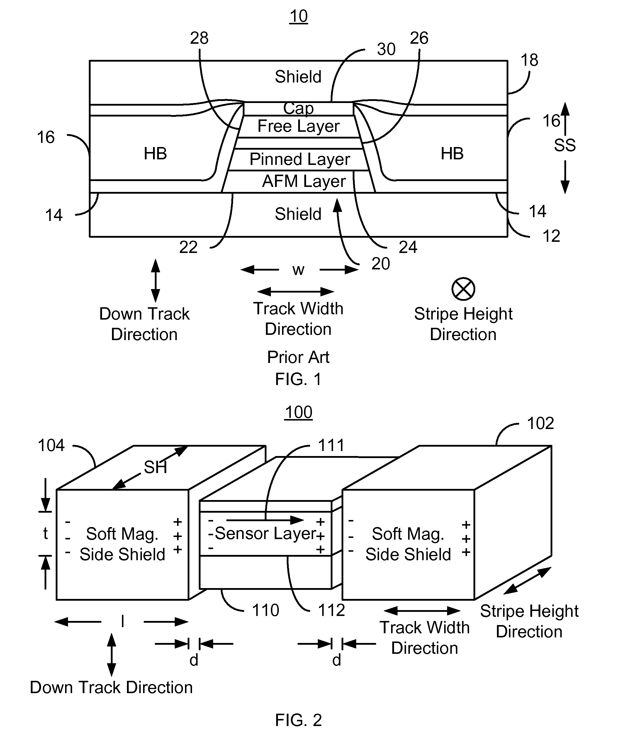
[0019]FIG. 2 depicts a perspective view of an exemplary embodiment of a portion of a magnetic read transducer 100. For clarity, FIG. 2 is not to scale. The read transducer 100 may be part of a read head or may be part of a merged head that also includes a write transducer. The head of which the read transducer 100 is a part is part of a disk drive having a media, a slider and the head coupled with the slider.

[0020]The transducer 100 includes a read sensor 110 and soft magnetic side shields 102 and 104. In general, the read transducer 100 will also include shields above and below the sensor 110. The sensor 110 includes a sensor layer 112. In some embodiments, the sensor 110 is a GMR or TMR sensor. Thus, the sensor layer 112 may be a free layer. The sensor 110 may also include a pinning layer such as an AFM layer, pinned layer, and a nonmagnetic spacer or barrier layer between the pinned and free layers. The sensor 110 may also include seed and / or capping layer(s). The nonmagnetic spa...


PUM


Abstract

A method and system for providing a magnetic transducer having an air-bearing surface (ABS) is described. The magnetic read transducer includes a first shield, a magnetoresistive sensor, at least one soft magnetic side shield, and a second shield. The magnetoresistive sensor includes a sensor layer having at least one edge in the track width direction along the ABS. The at least one soft magnetic side shield is adjacent to the at least one edge of the sensor layer. The at least one soft magnetic side shield has a full film permeability of at least ten. The magnetoresistive sensor is between the first shield and the second shield and free of an in-stack hard bias layer.

Description

BACKGROUND[0001]FIG. 1 depicts an air-bearing surface (ABS) view of a conventional read transducer used in magnetic recording technology applications. The conventional read transducer 10 includes shields 12 and 18, insulator 14, hard bias structures 16, and sensor 20. The read sensor 20 is typically a giant magnetoresistive (GMR) sensor or tunneling magnetoresistive (TMR) sensor. The read sensor 20 includes an antiferromagnetic (AFM) layer 22, a pinned layer 24, a nonmagnetic spacer layer 26, and a free layer 28. Also shown is a capping layer 30. In addition, seed layer(s) may be used. The free layer 28 has a magnetization sensitive to an external magnetic field. Thus, the free layer 28 functions as a sensor layer for the magnetoresistive sensor 20. Consequently, as used herein a sensor layer 28 is typically a free layer.[0002]If the sensor 20 is to be used in a current perpendicular to plane (CPP) configuration, the insulator 14 is used. Thus, current is driven in a direction subst...

Claims


Application Information

Patent Timeline
IPC IPC(8): G11B5/39
CPCB82Y10/00G11B5/3912G11B5/3909G11B2005/3996
Inventor MAURI, DANIELEHU, CHIH-CHINGMAO, MINGHO, KUOK SANGIDER, SAVAS
Owner WESTERN DIGITAL TECH INC
Why Eureka
Try Eureka