Eureka AIR delivers breakthrough ideas for toughest innovation challenges, trusted by R&D personnel around the world.

Biometrics based identification

Active Publication Date: 2014-01-14
TELECOM ITALIA SPA
View PDF4 Cites 15 Cited by
  • Summary
  • Abstract
  • Description
  • Claims
  • Application Information

AI Technical Summary

Benefits of technology

The patent aims to solve the problem of two biometric templates not being easily matched because of their rotation during identification. The solution proposed is to impose a constraint on the user's ability to rotate the position of the biometric characteristic, such as their finger, during identification. This approach avoids the need for rotating one template with respect to the other, which would require using trigonometric functions.

Problems solved by technology

The biometric characteristics are complex and thus represented by large electronic representations (images, voice signals etc.), and their detection, though preserving the uniqueness of the biometric characteristic itself, is subject to changes and errors.
Biometric template matching thus generally requires a great deal of memory and computational resources to carry out the alignment step.
The document recognises that a matching algorithm run on a smart card faces significant constraints because of the restricted resources of the smart card, especially the non-availability of floating point coprocessors.
Furthermore, the search for the transformation requires trigonometric functions, that are not available in standard smart cards.

Method used


Image

  • Biometrics based identification
  • Biometrics based identification
  • Biometrics based identification

Examples


Embodiment Construction

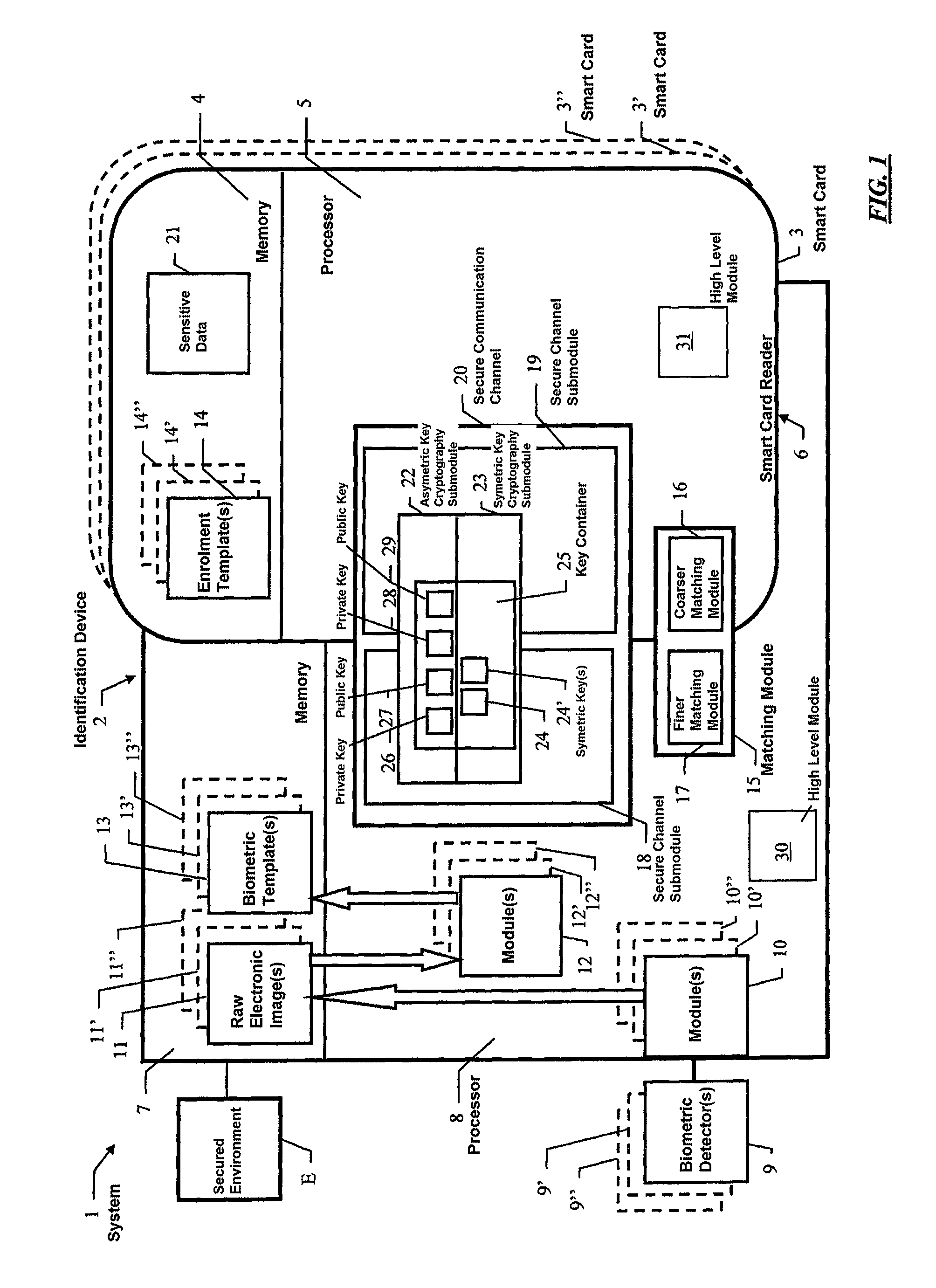
[0046]In FIG. 1 a block diagram of a preferred embodiment of a biometrics based identification system 1 according to the invention is shown.

[0047]System 1 comprises a biometrics based identification device 2 and at least one portable data carrier with processor 3, 3′, 3″ . . . , such as a smart card of the microprocessor card type, e.g., a SIM or USIM. For the sake of brevity, portable data carrier with processor 3 will be often referred to as smart card 3 hereinafter. Smart card 3 comprises a memory 4 and a processor 5.

[0048]Biometrics based identification device 2 is part of, or capable of electronically communicating with, a secured environment E, to grant or deny access to secured environment E to a purported user upon identification through the biometrics based identification system 1.

[0049]Secured environment E can be any of a variety of environments, e.g. a computer or computer network comprising sensitive data such as personal data or sensitive applications such as financial...


PUM


Abstract

A biometrics template matching method includes the steps of: providing a reference biometric template and a candidate biometric template, each including position data and orientation data of a respective plurality of minutiae; comparing the orientation data of each minutia from the candidate template with the orientation data of each minutia from the reference template; when the orientation data of a selected pair differ by no more than a first threshold, determining a displacement vector representative of the difference in position data of the selected pair of minutiae; determining the maximum number of displacement vectors that differ from each other by less than a second threshold; if the maximum number of displacement vectors is less than a third threshold, returning a mismatch, otherwise returning a match.

Description

CROSS REFERENCE TO RELATED APPLICATION[0001]This application is a national phase application based on PCT / EP2007 / 011421, filed Dec. 24, 2007, the content of which is incorporated herein by reference.BACKGROUND OF THE INVENTION[0002]1. Field of the Invention[0003]The present invention relates generally to the field of biometrics based identification, and more particularly to a biometrics template matching method, a biometrics based identification method, device and system, as well as a portable data carrier with processor and a secured electronic system.[0004]2. Description of the Related Art[0005]There is an increasing need for univocally identifying a person before granting or refusing access to a secured environment, e.g. for securing access to sensitive data or applications in computers and computer networks, for securing access to restricted areas, for securing transactions, for digitally signing electronic documents and so on.[0006]Identification through use of biometrics (“wha...

Claims


Application Information

Patent Timeline
IPC IPC(8): G06F21/00G06F21/32
CPCG06K9/00087G06F21/32G06V40/1365G06V40/55
Inventor BALDAN, SIMONEVENDITTELLI, PAOLO
Owner TELECOM ITALIA SPA
Why Eureka
Eureka Blog
Learn More