Pipe joint construction

a technology of pipe joints and joints, applied in the direction of hose connections, pipe couplings, couplings, etc., can solve the problems of requiring a great deal of labor and effort in the disassembly operation, and disadvantageous relative rotation operations, and achieve the effect of maintaining reliably

Active Publication Date: 2014-01-21
TOKYO METROPOLITAN GOVERNMENT +1
View PDF16 Cites 9 Cited by
  • Summary
  • Abstract
  • Description
  • Claims
  • Application Information

AI Technical Summary

Benefits of technology

[0046]According to the characteristic construction noted above, when the elastic urging member is attached between the inclined receiving face formed in the extending portion of the lock member and the outward surface of the annular wall portion, the elastic restoring force of the elastic urging member in the diameter-decreasing direction can be efficiently ...

Problems solved by technology

This involves a great deal of labor and effort in the disassembling operation...

Method used


Image

  • Pipe joint construction
  • Pipe joint construction
  • Pipe joint construction

Examples


first embodiment

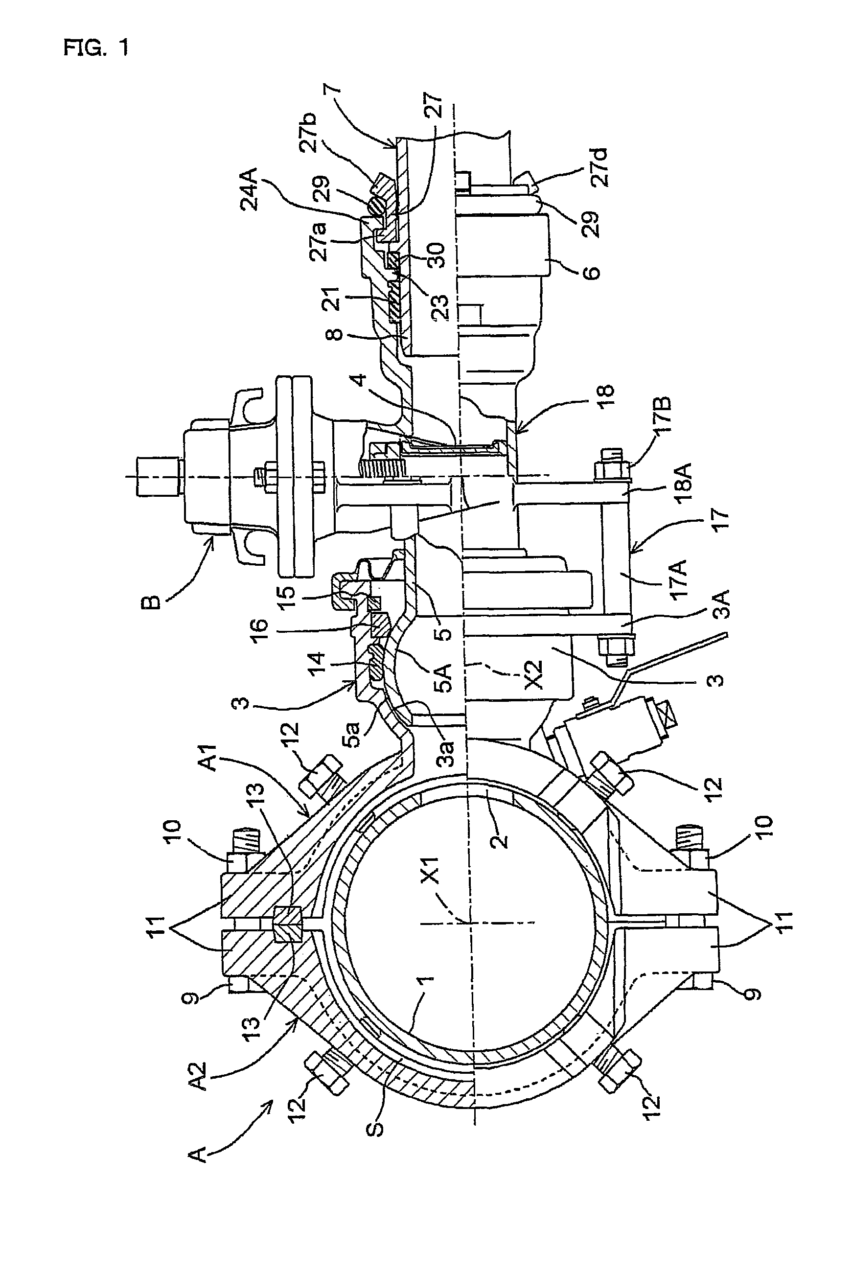
[0058]FIGS. 1 through 9 illustrate a pipe joint construction provided in a pipeline system of a water pipe 1 as one example of fluid pipes.

[0059]A cast-iron joint body A attached to the cast-iron water pipe 1 comprises two split joint segments A1 and A2 fitted on the water pipe 1 to be detachably and fixedly coupled to each other along a pipe peripheral direction (circumferential direction).

[0060]A branch receiving pipe section 3 protrudes outwardly and integrally from one of the split body segments A1 to communicate coaxially with a through bore 2 formed in a peripheral wall of the water pipe 1 from a direction of a second pipe axis X2 perpendicular to a direction of a first pipe axis X1 of the water pipe 1. An inserted pipe section 5 of a sluice valve B having a valve member 4 for opening and closing a branch fluid passage is hermetically fitted into and connected to the branch receiving pipe section 3 to be flexible in three-dimensional directions.

[0061]Further, the sluice valve ...

second embodiment

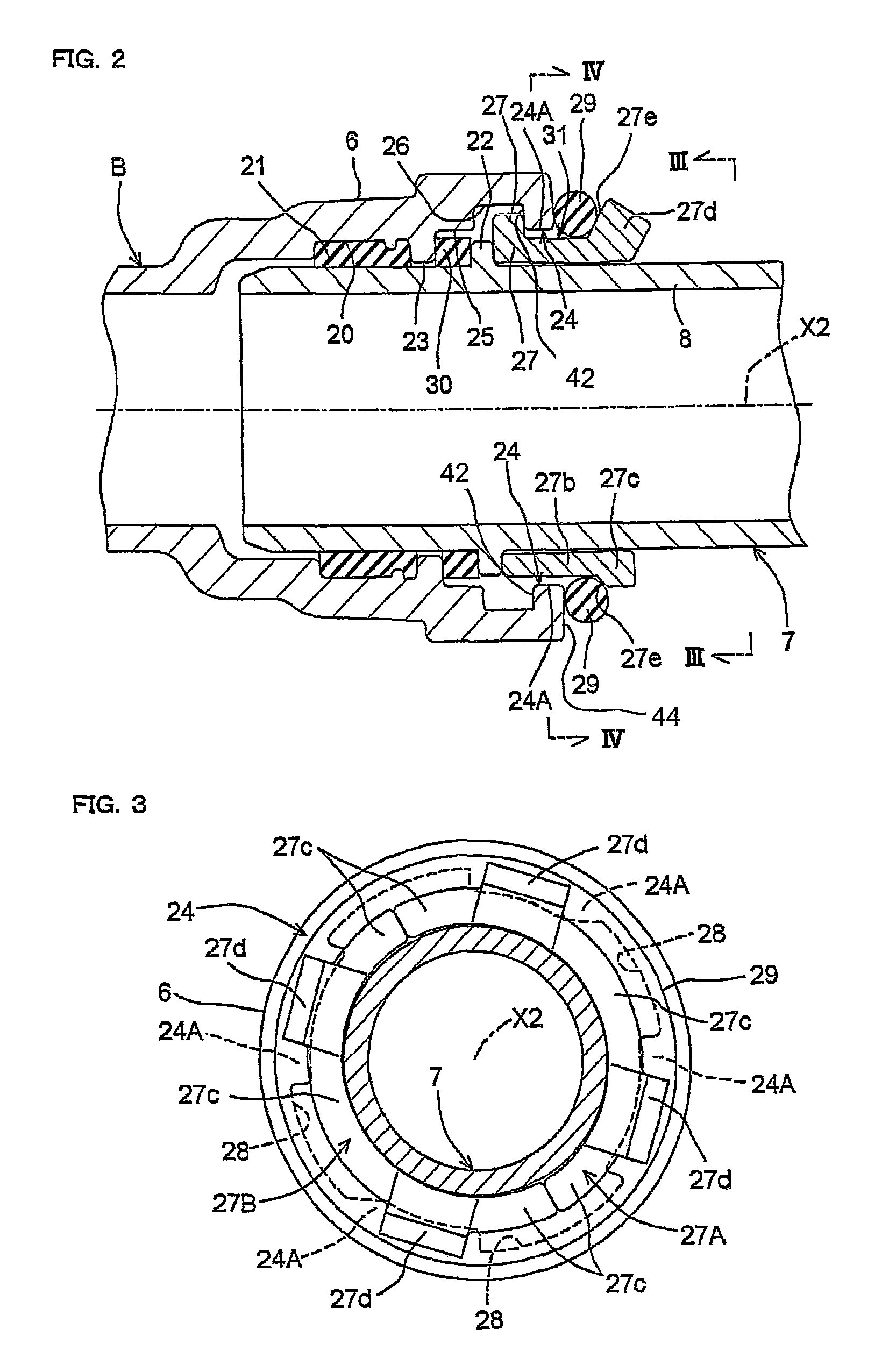
[0110]In the first embodiment described above, the engaging projection 22 is formed to project integrally from the outer peripheral surface of the inserted pipe section 8, and the lock member 27 consists of the split lock pieces 27A and 27B. The split lock pieces 27A and 27B are attached to the outer peripheral surface of the inserted pipe section 8 from radially outward, but other constructions may be employed.

[0111]As shown in FIG. 10, for example, the lock member 27 may have an annular integral construction, while a generally C-shaped engaging projection 22 which is elastically deformable in a diameter-increasing direction may be detachably attached to a mounting groove 8a formed in the outer peripheral surface of the inserted pipe section 8. The lock member 27 may be attached to the outer peripheral surface of the inserted pipe section 8 from the direction of pipe axis.

[0112]Since the other aspects of the construction are the same as those described in the first embodiment, like...

third embodiment

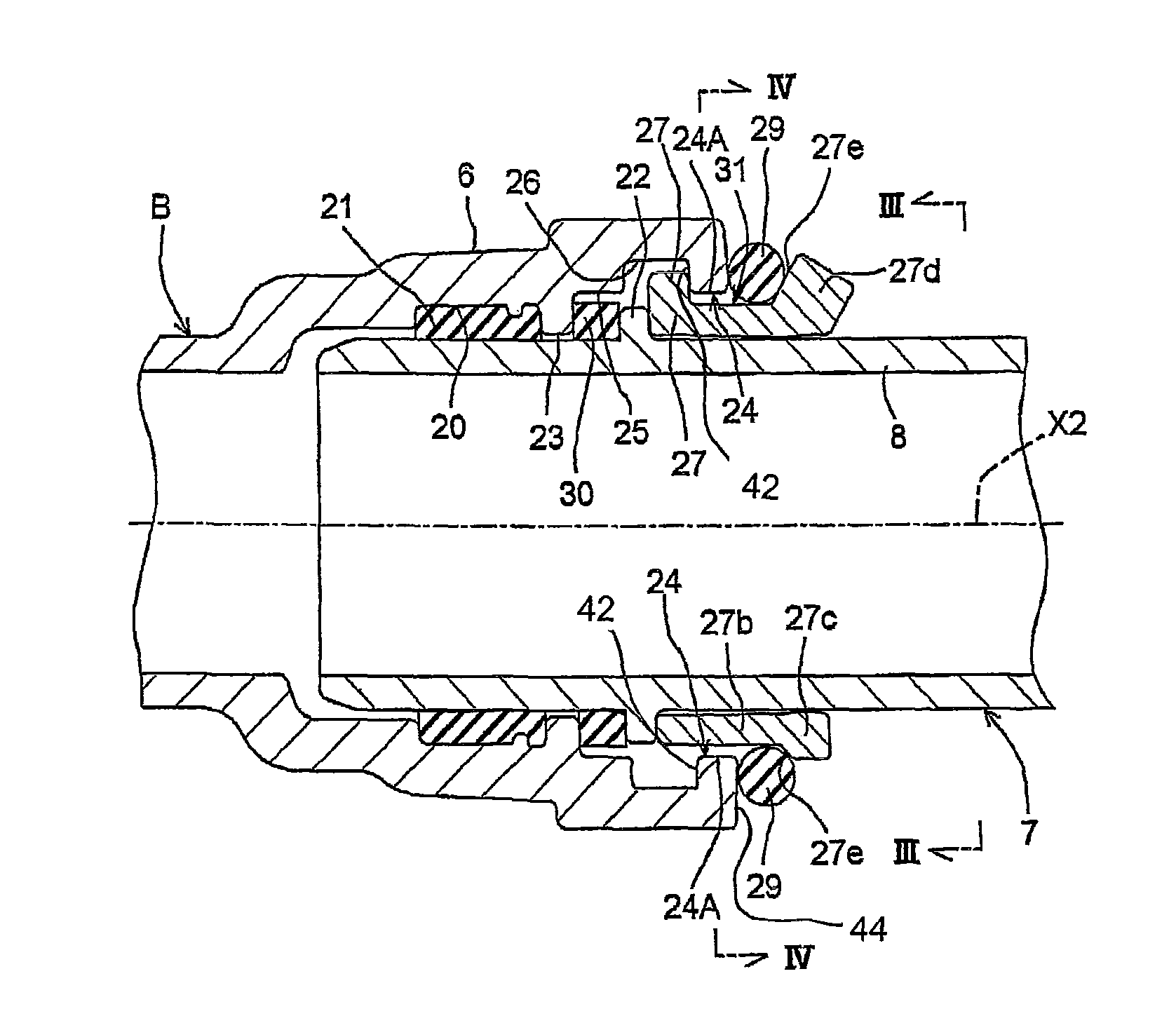
[0113]In the first embodiment described above, the second elastic urging member 30 is provided between the stopper wall portion 23 of the receiving pipe section 6 and one side face of the engaging projection 22 in a slightly compressed condition when both the pipe sections 6 and 8 are in a predetermined connected condition. Also, the first elastic urging member 29 is provided between the receiving faces 27e of the lock member 27 and the outward surface of the annular wall portion 24 in a slightly compressed condition. Thus, both the pipe sections 6 and 8 are connected to each other not to be substantially extendible and contactable along the second pipe axis P2. However, other constructions may be employed.

[0114]As shown in FIG. 11, for example, the second elastic urging member 30 may be omitted, and spaces S1 and S2 corresponding to extending / contracting operation distances between the pipe sections 6 and 8 may be formed between the stopper wall portion 23 and one side face of the ...


PUM


Abstract

A lock member capable of contacting an engaging projection of an inserted pipe section from a direction of the pipe axis and relatively rotatably attachable between an annular wall portion of a receiving pipe section and the engaging projection of the inserted pipe section includes engaging stopper portions projecting therefrom for contacting an inward surface of the annular wall portion from the direction of the pipe axis. The annular wall portion has attachment/detachment recesses formed therein for allowing inserting and removing movements of the engaging stopper portions in the direction of the pipe axis. An elastic urging member is provided between an extending portion projecting from the lock member to the outside of the pipe through an inner peripheral surface of the annular wall portion and the outer peripheral surface of the inserted pipe section, and an outward surface of the annular wall portion.

Description

BACKGROUND OF THE INVENTION[0001]1. Field of the Invention[0002]The present invention relates to an improvement in a pipe joint construction for enhancing a separation preventive function between a receiving pipe section and an inserted pipe section inserted into and connected to the receiving pipe section from a direction of pipe axis, the pipe sections constituting part of a fluid pipeline system such as a water pipeline system or the like.[0003]2. Description of Related Art[0004]Conventionally, the following techniques have been known as pipe joint construction enhancing the separation preventive function between the receiving pipe section and the inserted pipe section.[0005](1) The receiving pipe section has, formed on / in inner peripheral surfaces thereof, an annular stopper wall portion for limiting a maximum inserted position (maximum contracting position) between the pipe sections by contacting, in a pipe axis direction, an annular engaging projection protruding from an outer...

Claims


Application Information

Patent Timeline
IPC IPC(8): F16L21/02
CPCF16L37/113F16L2201/80F16L27/12
Inventor HORIKAWA, GOMIYAZAKI, FUMIYOSHI
Owner TOKYO METROPOLITAN GOVERNMENT
Why Eureka
Try Eureka