System for holography

a holographic display and system technology, applied in the field of recording holograms, can solve the problems of limited use and high cost, devices without memory, and inability to generate arbitrary scenes by holographic displays, so as to reduce the angle, and increase the diffraction efficiency of pr polymer.

Active Publication Date: 2014-01-21
TIPD
View PDF11 Cites 61 Cited by
  • Summary
  • Abstract
  • Description
  • Claims
  • Application Information

AI Technical Summary

Benefits of technology

[0022]The present invention provides methods of recording holograms that reduce the writing time, increase the diffraction efficiency, improve the resolution, or restitute color. These techniques are well suited for use with an updateable 3D holographic display using integral holography and photorefractive polymer.
[0024]In an embodiment in which the holographic recording material comprises a photorefractive (PR) polymer, a holographic optical element (HOE) diffracts one of the object or reference beams to reduce the angle between the grating vector and the external dielectric field and increase the diffraction efficiency of the PR polymer. In one configuration the HOE is configured to allow one of the object or reference beams to pass there through and to diffract the other beam to reduce the angle between the grating vector and the external electric field to increase the diffraction efficiency of the PR polymer.
[0025]In an embodiment in which the system is configured for a transmission geometry and recording a full-parallax holographic stereogram, a first lens array focuses the object beam on the recording material at multiple positions. The object beam is spatially structured so that each position corresponds to the correct hogel data. A second lens array splits the reference beam into multiple reference beams that are directed to the first lens array that collimates the multiple reference beams. If the beams overlap each other at the second lens array, the array is implemented as a HOE including an angularly selective grating to let the object beam pass unaffected while splitting and redirecting the reference beams. The second lens array may be implemented as a HOE that also diffracts the reference beams to reduce the angle between the grating vector and the external dielectric field and increase the diffraction efficiency of the PR polymer. The multiple object and multiple reference beams interfere at the multiple positions on the material to write multiple hogels simultaneously. The lens arrays may also be configured for HPO or reflective geometry as well.
[0030]In an embodiment in which the hologram is recorded using integral holography for a display and the modulated object beam is spatially structured with hologram data for multiple holograms, a first HOE splits and diffracts the reference beam into multiple reference beams, a second HOE collimates the multiple reference beams and focuses the object beam so that the multiple object and multiple reference beams interfere at multiple positions on the material to write multiple holograms simultaneous, and a third HOE positioned after the recording material to redirect a reading beam transmitted through the recording beam approximately orthogonal to the recording material toward a viewer position to provide a more natural look at the display.
[0032]In an embodiment in which the system is configured to record hologram(s) on a dynamic holographic recording material comprising a PR polymer, the object beam is used to simultaneously erase the structure of the previous hologram and write the current hologram. The laser power is high enough to erase the previous hologram without leaving a ghost image and low enough to record the current hologram without causing a permanent set. In a configuration, the object beam reduces the diffraction efficiency of the previous hologram to less than 20% when writing the current hologram.
[0034]In an embodiment in which the holographic recording material comprises a PR polymer, a pair of interleaved electrodes is deposited on one surface of the PR polymer. With such a pattern, the orientation of the electric field is parallel to the sample surface if the sample is thin compared to the space between the electrodes. If the plane of incidence (plane comprising both writing beams) has a component parallel to the field vectors, the grating vector will also have a component along the electric field and the photorefractive effect will occur.

Problems solved by technology

While holography is commonly used to display static 3-D pictures and simple 3D images have been successfully rendered, the generation of arbitrary scenes by a holographic display is not yet possible.
Current commercially available holographic 3D displays employ material like photopolymers or silver halide emulsion that lack image-updating capability, resulting in their restricted use and high cost.
Unfortunately, these devices do not have memory, and thus do not exhibit persistence of recorded images.
The lack of persistence results in the requirement of update rates faster than 30 Hz to avoid image flicker.
Since 3D images exhibit very high information content, this high refresh rate requirement currently limits real time holographic displays to small sizes or low resolution.
Although updateable, PR polymers have not yet been used for 3D displays because of their long writing times and low persistence.
The resolution limitation now comes from the optical recording setup resolution that is usually orders of magnitude higher than regular lens array resolution.

Method used


Image

  • System for holography
  • System for holography
  • System for holography

Examples


Embodiment Construction

[0056]The present invention provides methods of recording holograms that reduce the writing time, improve the resolution, increase the efficiency, or restitute color. These techniques are well suited for use with an updateable 3D holographic display using integral holography. These techniques may be used individually or in combination.

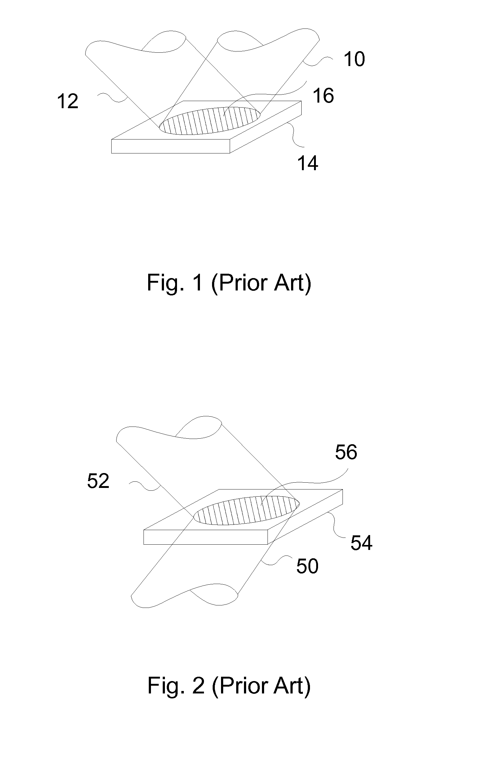
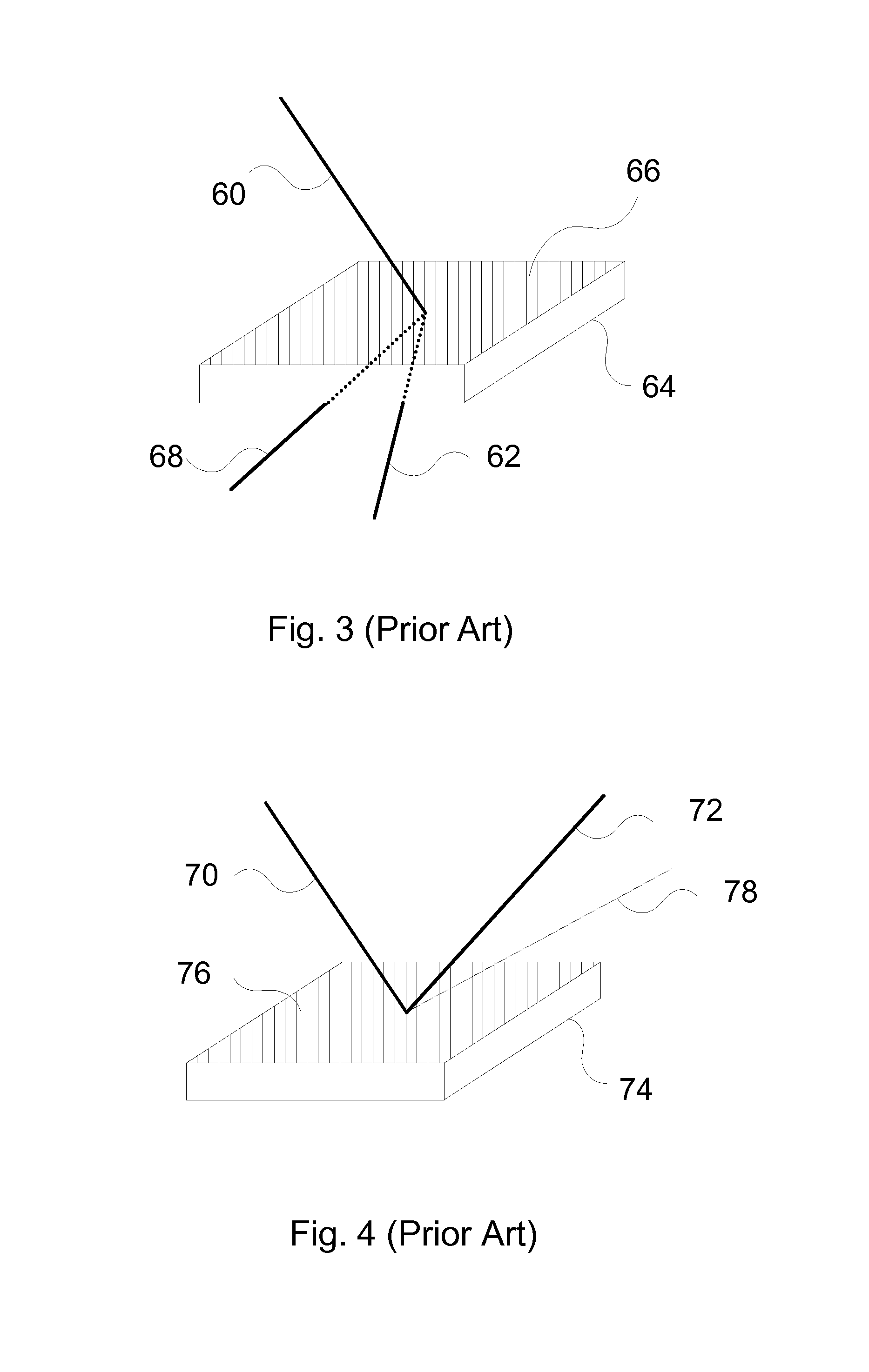
[0057]In photorefractive polymer materials the diffraction efficiency strongly depends on the angle between the grating vector and the external applied field direction. The grating vector is perpendicular to the bisector of the object and reference beams inside the recording material. The diffraction is minimum when this angle is 90° and maximum when this angle is 0°. This is due to the charge transport mechanism that is governed by drift. When using a PR polymer it is important to minimize this angle to optimize the diffraction efficiency. For transmission gratings, this is achieved by using a non-symmetrical geometry where the sample is tilted accord...


PUM

PropertyMeasurementUnit
external electric fieldaaaaaaaaaa
electric fieldaaaaaaaaaa
angleaaaaaaaaaa

Abstract

The present invention provides systems of recording holograms that reduce the writing time, increase the diffraction efficiency, improve the resolution, or restitute color. These systems are well suited for use with an updateable 3D holographic display using integral holography and photorefractive polymer.

Description

CROSS-REFERENCE TO RELATED APPLICATIONS[0001]This application claims benefit of priority under 35 U.S.C. 119(e) to U.S. Provisional Application No. 61 / 363,165 entitled “System and Method for Holography” and filed on Jul. 9, 2010, the entire contents of which are incorporated by reference.GOVERNMENT LICENSE RIGHTS[0002]This invention was made with Government support under contracts FA9550-10-C-0009 awarded by the Air Force Research Laboratory (AFRL), W31P4Q-07-C-0267 awarded by the U.S. Army Aviation & Missile Command and FA8650-10-C-7034 awarded by the Office of the Director of National Intelligence (ODNI). The Government has certain rights in this invention.BACKGROUND OF THE INVENTION[0003]1. Field of the Invention[0004]This invention relates to recording holograms and, more particularly, to methods and techniques to improve the quality, recording speed, efficiency and color displaying of holograms. These methods may find particular applications with photorefractive polymers or oth...

Claims


Application Information

Patent Timeline
Patent Type & Authority Patents(United States)
IPC IPC(8): G03H1/12G03H1/00G11B7/0065G03H1/26
CPCG03H2223/19G03H1/04G03H1/26G03H1/02G03H2001/303G03H2260/35G03H2223/23G03H1/0011G03H2260/54G03H2001/0264G03H2001/0482G03H2001/2271G03H2210/22G11B7/0065
Inventor BABLUMYAN, ARKADYBLANCHE, PIERRE-ALEXANDRE JEANPEYGHAMBARIAN, NASSER N.
Owner TIPD
Why Eureka
Try Eureka