
Sound transmitting device

a technology of sound transmission and transmission device, which is applied in the direction of combustion-air/fuel-air treatment, fuel intake silencer, machine/engine, etc., can solve the problems of high pitch and unpleasant, engine operating sound level may become further obscured, and introduce frequency dependent distortion in the sound level and sound quality transmitted, so as to achieve balanced sound

Active Publication Date: 2014-01-21
MANN HUMMEL GMBH
View PDF6 Cites 5 Cited by
  • Summary
  • Abstract
  • Description
  • Claims
  • Application Information

AI Technical Summary

Benefits of technology

This patent describes a system where a porous material is placed in the sound transmission line between two ends. This helps to make the sound more balanced and uniform throughout the vehicle. The system also uses branches to direct the sound to specific areas. Overall, this results in a better sound quality in the vehicle interior.

Problems solved by technology

The use of turbocharged engines have also caused the natural sounds of the engine to be masked by noise coming from the turbo which are high pitched and unpleasant.
Additionally the engine operating sound level may become further obscured by the presence of other secondary noises such as vehicle HVAC systems, etc.
Unfortunately, such elastomeric diaphragms may also introduce frequency dependent distortions in the sound level and sound quality transmitted into the passenger compartment and experienced by the driver.

Method used


Image

  • Sound transmitting device
  • Sound transmitting device
  • Sound transmitting device

Examples


third embodiment

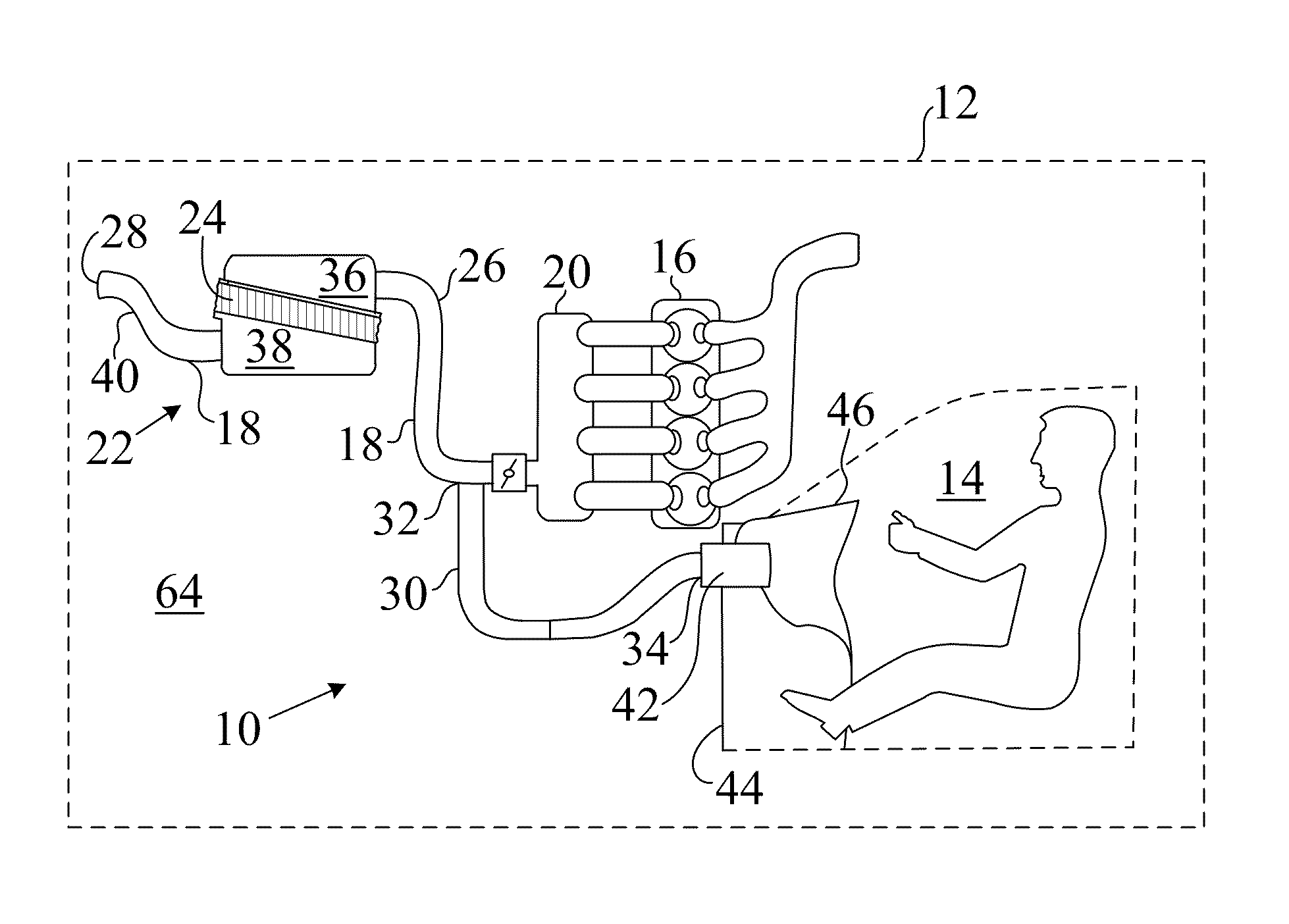
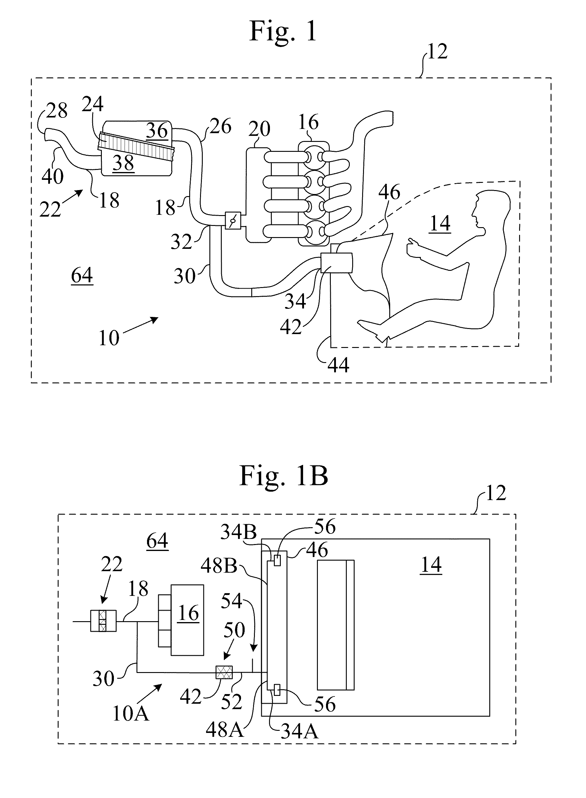
[0045]In the invention, the porous media 42 is arranged in a location in the sound transmission line 30 between its two opposing ends (32 and 34), porous media is positioned as illustrated in FIG. 1B but in other aspects essentially the configuration of FIG. 1. In this embodiment the porous media 42 divides the sound transmission line 30 into two sections, where airflow and transmitted sound is required to flow through the porous media 42 to travel between the sections. Advantageously, this embodiment removes the porous media 42 (which is preferably configured as an air filter media) from within the vehicle interior, providing a cleaner interface between the sound transmission line 30 and its mounting location, for example under or behind the dashboard 46 or connected into the HVAC ducting of the vehicle. Without the porous media 42 at the second end 34, the sound transmission line 30 may be of relatively small diameter where it enters the vehicle interior 14, its small size advanta...

fifth embodiment

[0047]In a fifth embodiment, the porous media is 42 is arranged in a location in the sound transmission line 30 between its two opposing ends (32 and 34) and dividing the sound transmission line 30 into two sections. The second portion of the sound transmission line 30 (for example, the portion 52 after the porous media 42 in FIG. 1B) may have a vent portion 54 that vents the sound transmission line 30 either directly or through a filter to the atmosphere. The vent 54 is particularly useful to further reduce the possibility of undesirable odors reaching the vehicle interior 14 from the air intake tract 18. The significant restriction to air flow offered by the porous media 42 relative to the restriction offered by the air filter 24 already makes this unlikely, although the vent 54 is an additional measure.

[0048]In a sixth embodiment, the porous media 42 is arranged in a location in the sound transmission line 30 between its two opposing ends (32 and 34) and dividing the sound transm...


PUM


Abstract

A device for transmitting engine sound into an interior of a motor vehicle includes a sound transmission line having a first end in acoustic communication with an air intake tract and a second end arranged to direct engine sound towards the motor vehicle interior. A sound transmitting porous media is arranged in-line with said sound transmission line and restricts airflow wherein the porous media such that airflow in the sound transmission line is required to pass through said porous media.

Description

TECHNICAL FIELD[0001]The invention relates to sound transmission devices for conducting engine sounds towards or into the passenger compartment of a motor vehicle.BACKGROUND OF THE INVENTION[0002]Various types of devices configured to conduct engine sound from the engine compartment of a motor vehicle into the passenger compartment are known. As engine designs evolve for great fuel efficiency, current varieties of motor vehicles have internal combustion engines that operate very smoothly so that the engine operating sound may be barely audible within the interior of the motor vehicle. A further reduction in engine sound may result from noise dampening foams and acoustic insulation arranged to limit the migration of road noise into the passenger compartment. The use of turbocharged engines have also caused the natural sounds of the engine to be masked by noise coming from the turbo which are high pitched and unpleasant. Additionally the engine operating sound level may become further...

Claims


Application Information

Patent Timeline
Patent Type & Authority Patents(United States)
IPC IPC(8): F02M35/12F01N1/02F01N1/24
CPCB60R13/08B60R13/0815
Inventor MAH, KEAT, BOON
Owner MANN HUMMEL GMBH
Learn More