
Systems and methods for monitoring operation of an LED string

a technology of led string and monitoring system, which is applied in the direction of discharge tube/lamp details, nuclear engineering, nuclear elements, etc., can solve the problem of large amount of electrical components needed to monitor a string of more than 4 leds

Active Publication Date: 2014-01-21
HONEYWELL INT INC
View PDF17 Cites 9 Cited by
  • Summary
  • Abstract
  • Description
  • Claims
  • Application Information

AI Technical Summary

Problems solved by technology

The disadvantage of this method is the large amount of electrical components needed to monitor a string of more than 4 LEDs.

Method used


Image

  • Systems and methods for monitoring operation of an LED string
  • Systems and methods for monitoring operation of an LED string
  • Systems and methods for monitoring operation of an LED string

Examples


Embodiment Construction

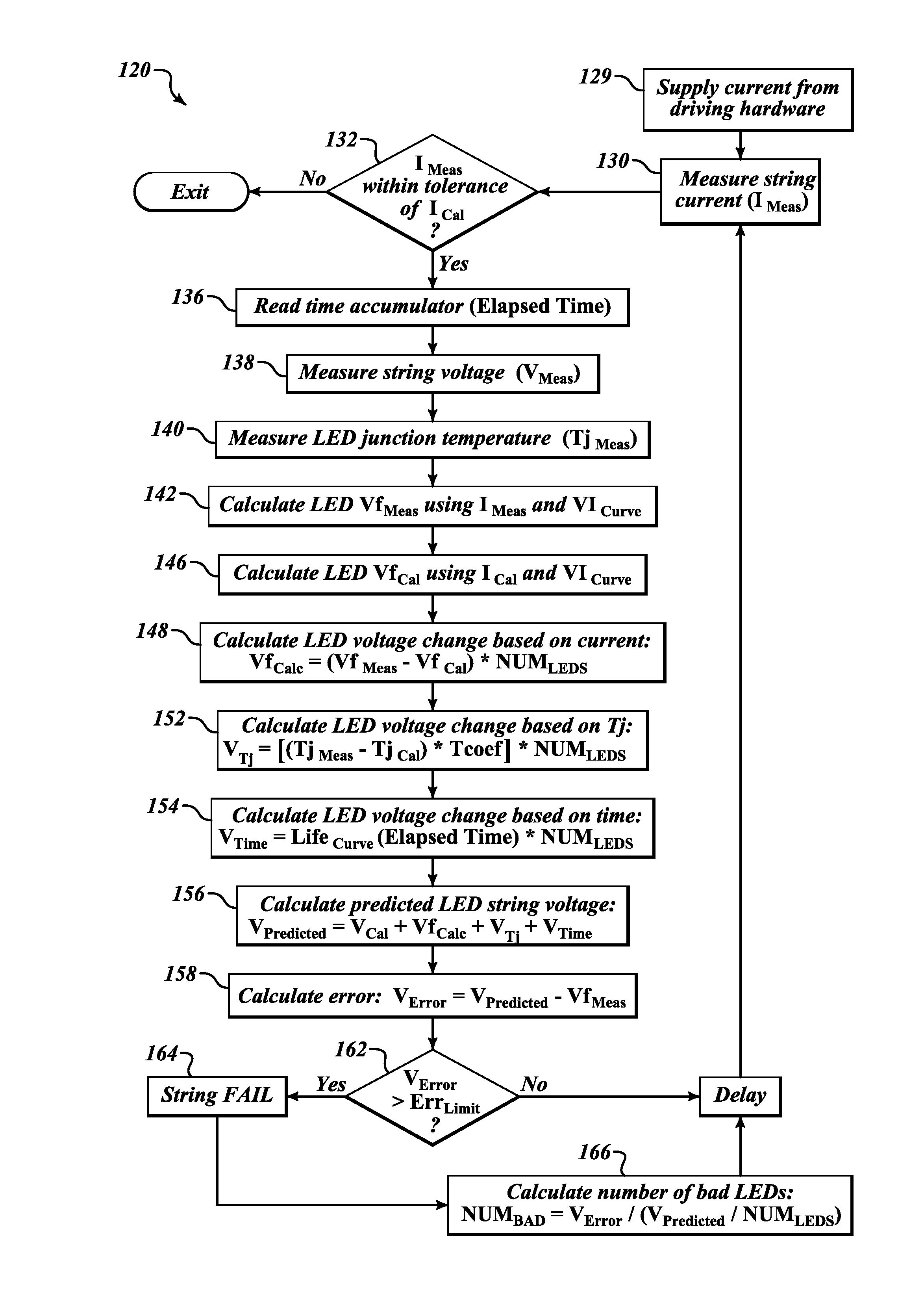
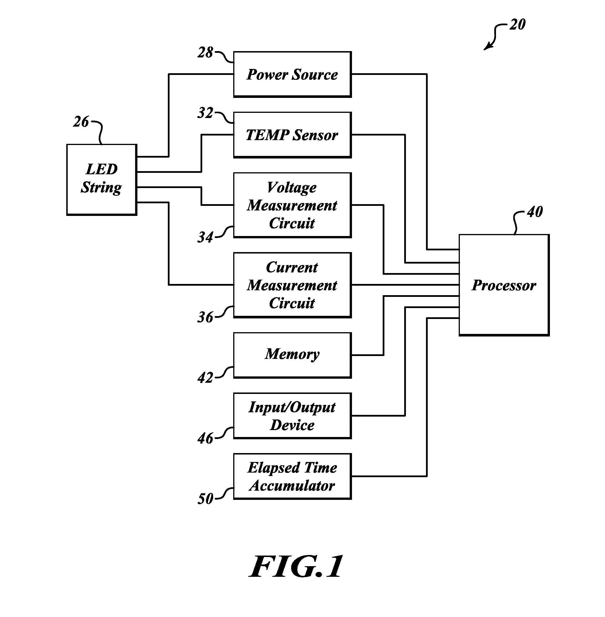
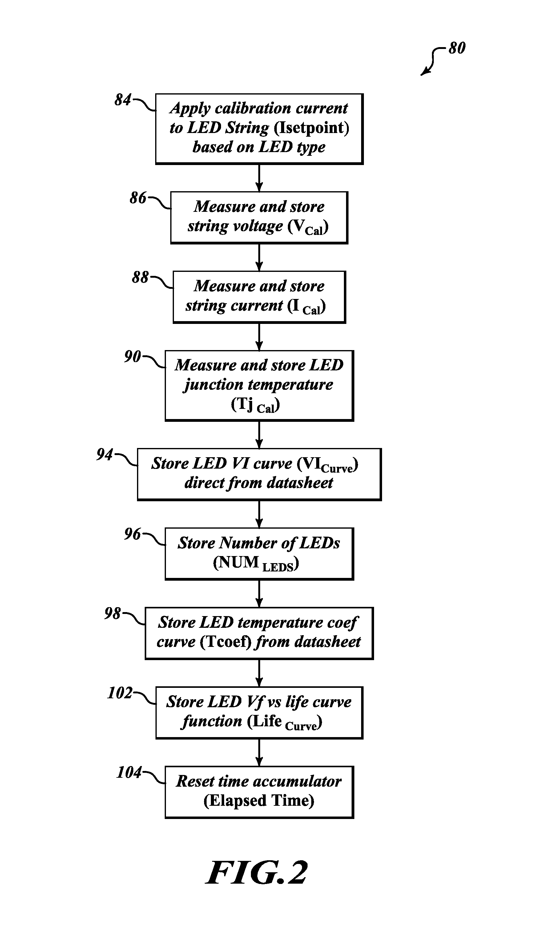
[0011]FIG. 1 illustrates an exemplary LED system 20 formed in accordance with an embodiment of the present invention. The system 20 includes an LED string 26, a voltage measuring circuit 34, a current measuring circuit 36, a temperature sensor 32, a power source circuit 28, a processor 40, an input / output device 46 and memory 42. The voltage measuring circuit 34, the current measuring circuit 36, and the power source circuit 28 are electrically connected to the LED string 26. The temperature sensor 32 is located proximate to the LED string 26. The processor 40 is in signal communication with the voltage measuring circuit 34, the current measuring circuit 36, the temperature sensor 32, the power source circuit 28, the input / output device 46, an elapsed time accumulator 50, and the memory 42.

[0012]The memory 42 includes various previously stored calibration parameters associated with the LED string 26. During operation of the LED string 26, the processor 40 monitors the values produce...


PUM


Abstract

Methods and systems for monitoring operation of an LED string. An exemplary system includes an LED string, a circuit that supplies current to the LEDs, a current measuring circuit that measures current through the LEDs, a voltage measuring circuit that measures voltage across the LEDs, and a temperature sensor that measures temperature proximate to the LEDs. A processor calculates a predicted string voltage based on a predefined voltage-current curve, number of LEDs, a predefined temperature coefficient value, the measured string current, a measured junction temperature, a life curve function, a prestored calibration string current value, a prestored calibration string voltage value, a prestored junction calibration temperature and an accumulated time value. The process also calculates an error value based on the predicted string voltage and a measured string voltage and generates an indication that there is a failure in the LED string if the calculated error value is greater than the predefined error limit.

Description

BACKGROUND OF THE INVENTION[0001]In aviation lighting there are stringent requirements on the amount of light that must be provided to meet minimum safety standards in some installations. In others, there are customer requirements that dictate how much light must be available. It is therefore desirous to know if any and how many light emitting diodes (LEDs) being used in a particular light are functioning properly.[0002]In high power LED general lighting implementations it is very desirous to place the LEDs in a single string so as to reduce the number electronic devices required to provide the proper current to the LEDs. The simplest way to verify that a single LED is functioning properly is to monitor the voltage across the LED when the proper drive current is applied. Complications with this method include several factors. Two well-known factors are the forward voltage of an LED is very sensitive to the junction temperature of the LED die and to the applied drive current. Thus ov...

Claims


Application Information

Patent Timeline
Patent Type & Authority Patents(United States)
IPC IPC(8): G06F17/40G01R31/36H05B33/08G06F19/00H05B44/00
CPCH05B33/0893G01R31/2635H05B45/58
Inventor DE OTO, LENPOLICY, RICHARDHODGE, STAN
Owner HONEYWELL INT INC
Learn More