
Solid state lighting system and maintenance method therein

a lighting system and solid state technology, applied in the direction of lighting and heating equipment, printed circuit non-printed electric components association, instruments, etc., can solve the problems of large heat sinks that may present problems for solid state light structures, damage to the pcb during a light emitter replacement, and the leds do not effectively conduct heat away from the led di

Inactive Publication Date: 2010-12-14
SEMILEDS OPTOELECTRONICS CO LTD
View PDF14 Cites 46 Cited by
  • Summary
  • Abstract
  • Description
  • Claims
  • Application Information

AI Technical Summary

Benefits of technology

[0009]Another embodiment of the invention provides a solid state lighting system. The lighting system generally includes a power supply coupled to one or more module interfaces; one or more solid state light modules, each module at least mechanically and electrically coupled to one of the module interfaces. Each of the solid state light modules generally includes a PCB, at least one LED, wherein the LED is coupled to the PCB via a solderless connection, and a first interface coupled to the PCB, for connection with one of the module interfaces.
[0010]Yet another embodiment of ...

Problems solved by technology

Since most LED semiconductor layers are formed on substrates of silicon, sapphire, or silicon carbide (SiC), the LEDs do not effectively conduct heat away from the LED die.
Large heat sinks may present problems for solid state light structures utilizing them.
These increased desoldering temperatures oftentimes hinder removal of a failed light emitter from a PCB in the field using a soldering iron and may lead to damage to the PCB during a light emitter replacement operation.
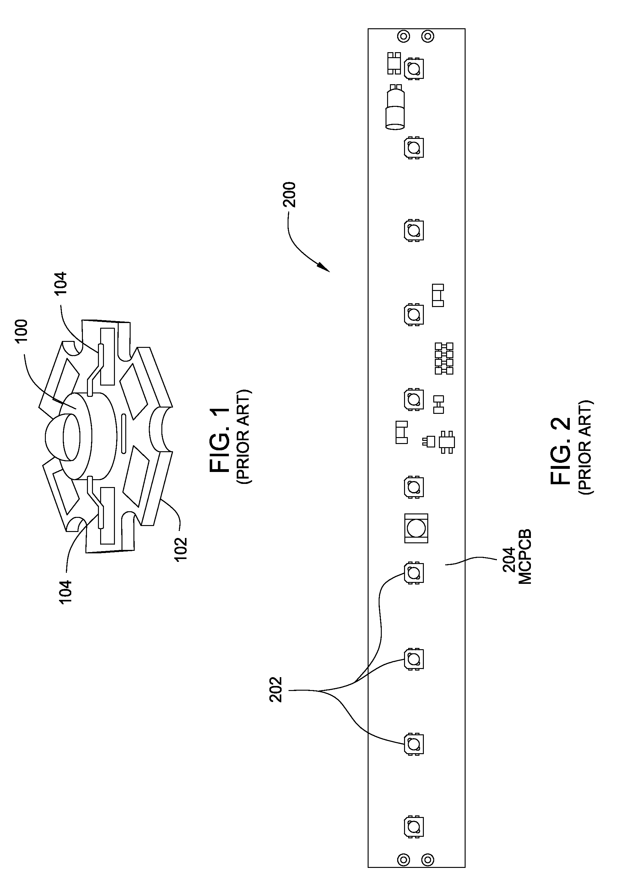
This problem is compounded when multiple solid state light emitters are necessary on a single light structure, and the spacing between light emitters is increased for proper heat dissipation capability of the heat sink (see FIG. 2).

Method used


Image

  • Solid state lighting system and maintenance method therein
  • Solid state lighting system and maintenance method therein
  • Solid state lighting system and maintenance method therein

Examples


Embodiment Construction

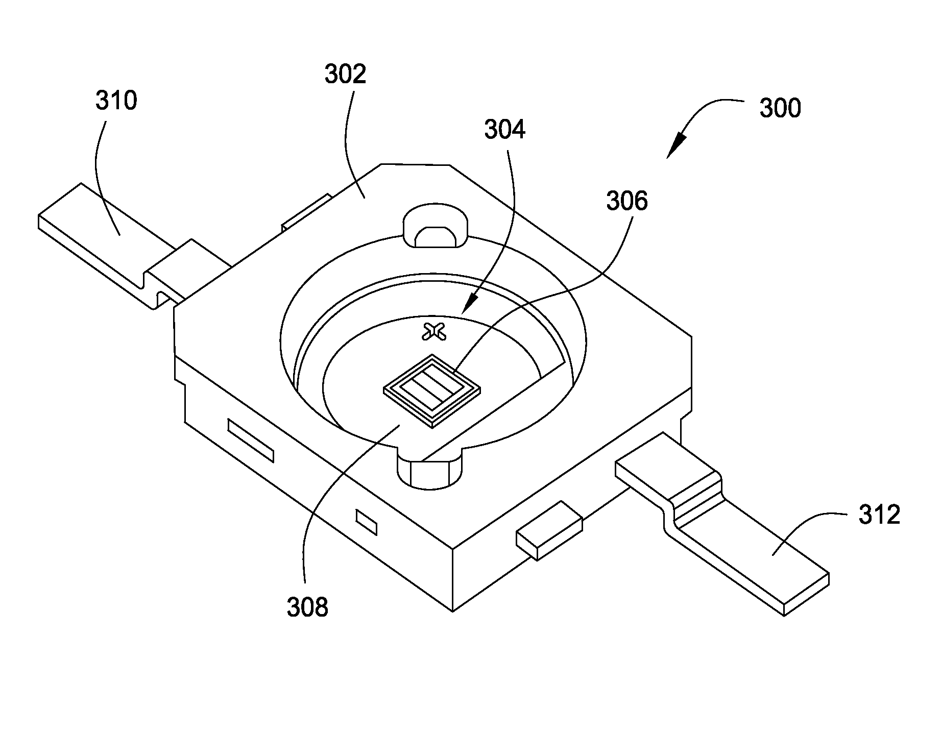
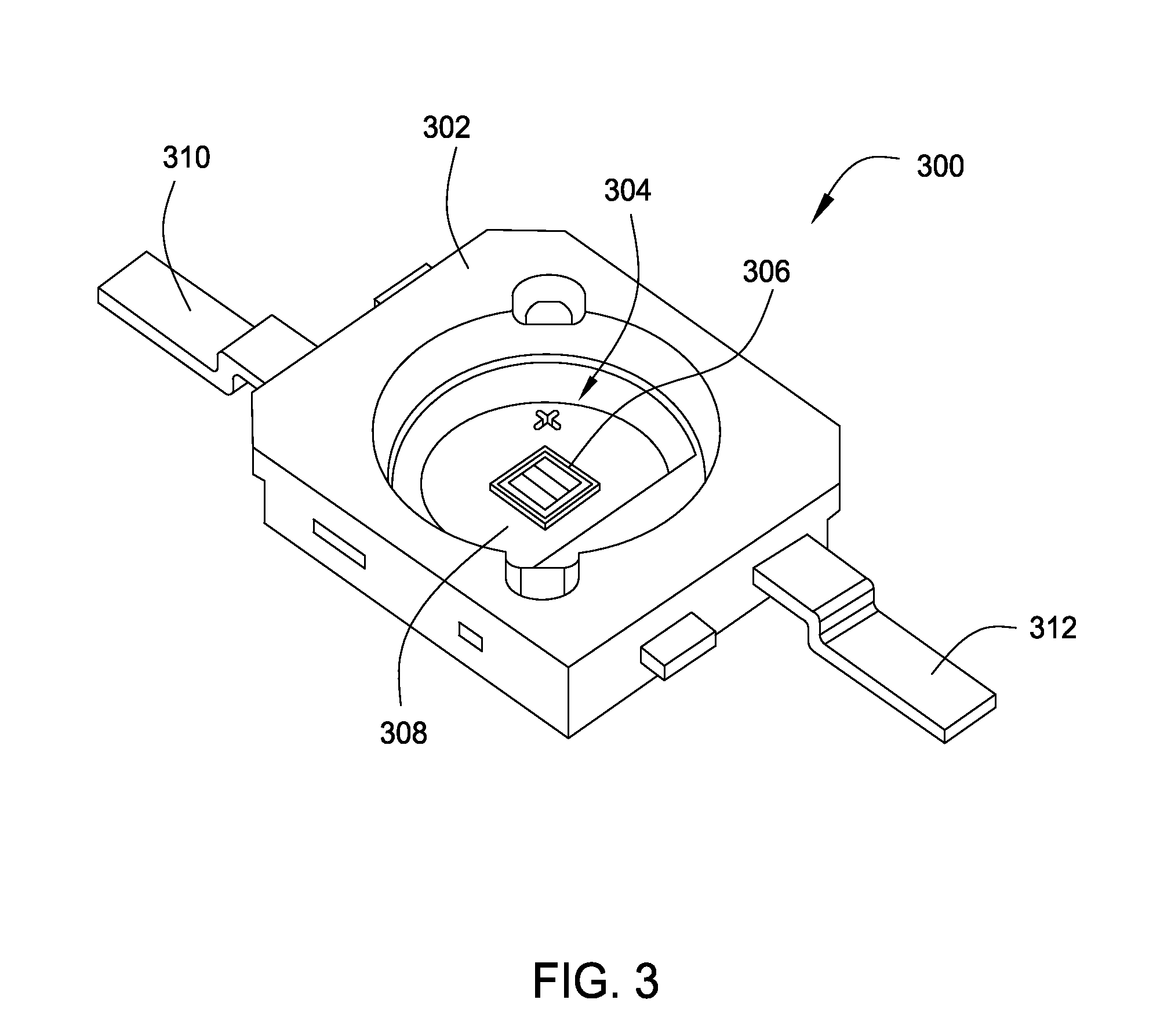
[0027]Embodiments of the present invention provide solid state light modules incorporating light emitting diodes (LEDs) and a solid state lighting system employing such modules. For some embodiments, the LED comprises a semiconductor structure for emitting light coupled to a metal substrate. The metal substrate may allow for lower LED junction temperature and, hence, a longer device lifetime. In addition, the metal substrate may allow for the potential omission of a heat sink, which may reduce light module size, when compared to conventional solid state light emitters.

[0028]For some embodiments, the light modules may utilize an interface between the LEDs and the remainder of the module such that installation and removal of the LEDs may be accomplished by mechanical force rather than by soldering / desoldering the leads to make / break the electrical contact. For these embodiments, failed LEDs may be manually replaced quickly at or near room temperature without the risk of damage to the ...


PUM


Abstract

A solid state light module incorporating light emitting diodes (LEDs) disposed on a metal substrate, a solid state lighting system employing such modules, and method of replacing LEDs of the light modules are provided. The metal substrate may allow for lower LED junction temperature and, hence, a longer device lifetime. In addition, the metal substrate may allow for the potential omission of a heat sink, which may reduce light module size, when compared to conventional solid state light emitters.

Description

BACKGROUND OF THE INVENTION[0001]1. Field of the Invention[0002]Embodiments of the present invention generally relate to solid state lighting systems and, more particularly, to interchangeable light modules having replaceable solid state light emitters.[0003]2. Description of the Related Art[0004]Advances in light-emitting diode (LED) luminous efficiency are allowing solid state emitters into numerous lighting applications that were previously unavailable. Solid state lighting is even replacing incandescent lighting technology in some applications where increased reliability is desired, especially in harsher environments where vibrations may occur (e.g., automobile taillights).[0005]However, the lifetime of an LED is dependent on the junction temperature, and the junction temperature is proportional to forward current. To approach the luminous intensity of other lighting technologies, LEDs may need to operated at relatively high forward currents (e.g., in the hundreds of milliamps),...

Claims


Application Information

Patent Timeline
IPC IPC(8): H05B41/16
CPCF21V23/06F21K9/13F21Y2101/02F21Y2105/001F21Y2105/10F21K9/23F21Y2115/10
Inventor YEN, JUI-KANGDOAN, TRUNG TRICHEN, YUNG-WEICHENG, CHING-TAI
Owner SEMILEDS OPTOELECTRONICS CO LTD
Learn More