LED junction temperature tester

a temperature tester and junction technology, applied in the direction of instruments, semiconductor/solid-state device details, optical radiation measurement, etc., can solve the problem of no instrument that can drive a led at a given current, and achieve the effect of simple calibration procedur

Inactive Publication Date: 2006-05-30
SHIH KELVIN
View PDF28 Cites 49 Cited by
  • Summary
  • Abstract
  • Description
  • Claims
  • Application Information

AI Technical Summary

Problems solved by technology

Currently, however, there is no instrument that can drive a LED at a given current and measure the corresponding junction temperature rise at the same time.

Method used


Image

  • LED junction temperature tester
  • LED junction temperature tester
  • LED junction temperature tester

Examples


Embodiment Construction

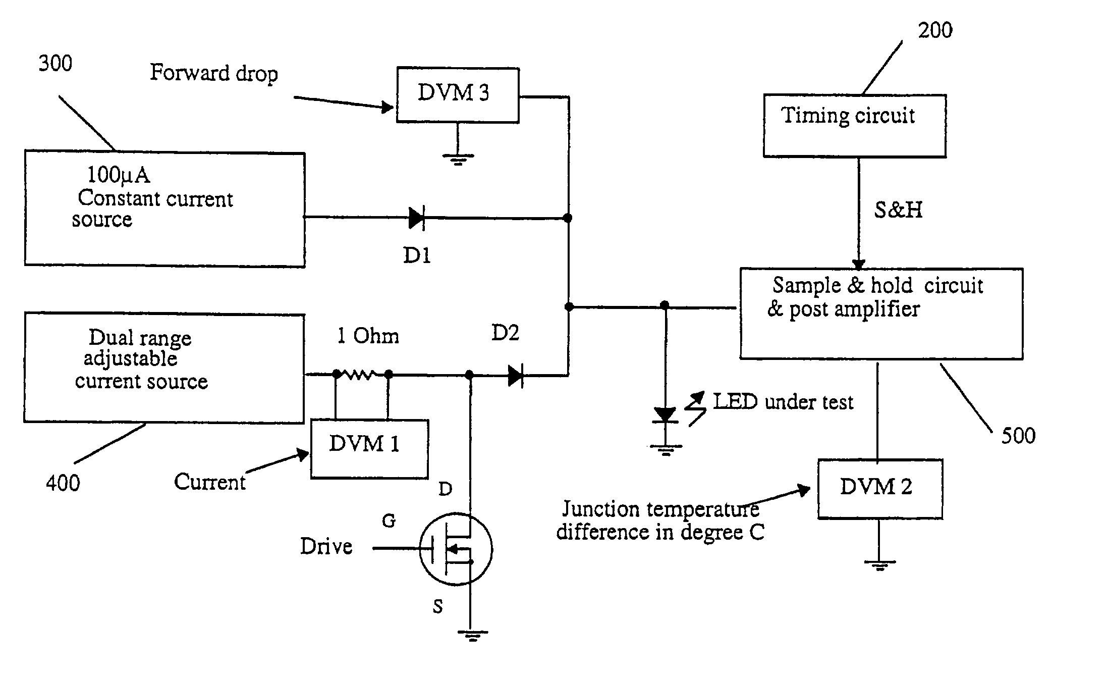
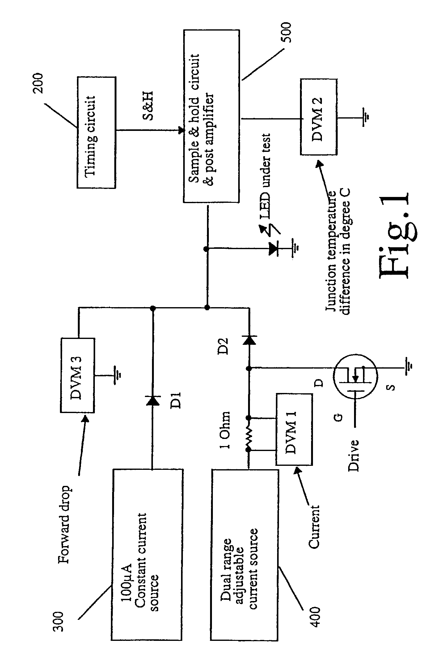
[0014]Generally, an LED junction temperature testing instrument according to the invention can read the temperature rise above the ambient in degrees C directly with a simple calibration procedure for a given LED family. In one embodiment, the forward drop of the LEDs can also be measured so that the calculation of the thermal resistance in ° C. / watt can be done easily.

[0015]The forward drop of LED (light emitting diode) is function of the forward current as well as the junction temperature. When the drive current increases, the forward drop will also go up. When the junction temperature increases, the forward drop decreases at a constant rate. As is known in the art, the relationship between the temperature and forward drop in LEDs is linear over the operating temperature range. To measure the junction temperature of the LED, the drive current used should be small enough to minimize any self-heating effects in the LED.

[0016]To start the calibration process, the instrument drives a ...


PUM

PropertyMeasurementUnit
temperatureaaaaaaaaaa
constant currentaaaaaaaaaa
currentaaaaaaaaaa

Abstract

An instrument measures the LED junction temperature directly by taking advantage of the linear relationship between the forward current driven through the LED, the forward drop of the LED, and the junction temperature to determine the LED junction temperature.Calibration is conducted by placing two LEDs from the same family in ambient temperature and passing a small test current through each of the LEDs to obtain the forward drop of the LED at ambient temperature. The LED under test is then placed in an environmentally-controlled chamber where the temperature is raised a known amount above ambient temperature. Known low and high voltage values are associated with the ambient temperature and the environmental chamber temperature, causing the LED under test becomes a calibrated thermometer that can measure its own junction temperature due to the linear relationship between the forward drop and the junction temperature.

Description

REFERENCE TO RELATED APPLICATIONS[0001]The present application claims priority to U.S. Provisional Patent Application No. 60 / 345,241, filed Jan. 4, 2002.BACKGROUND OF THE INVENTION[0002]High intensity LEDs are becoming more popular as light sources for traffic lights, automobile interior and exterior lighting, signboards, and other applications. The light output of a silicon LED chip is not only a function of the chip size and the process, but also a function of the junction temperature of the LED. By keeping the junction temperature low, LEDs can be driven with twice or three times as much current and, thus, generate twice or three times the light output while still extending the life of the LEDs. Currently, however, there is no instrument that can drive a LED at a given current and measure the corresponding junction temperature rise at the same time.[0003]There is a desire for an instrument that can measure a relationship between LED junction temperature and drive current.SUMMARY ...

Claims


Application Information

Patent Timeline
Patent Type & Authority Patents(United States)
IPC IPC(8): G01K15/00G01J5/20G01K7/01G01R31/26
CPCG01K7/01G01R31/2635H01L2924/0002H01L2924/00
Inventor SHIH, KELVIN
Owner SHIH KELVIN
Why Eureka
Try Eureka