

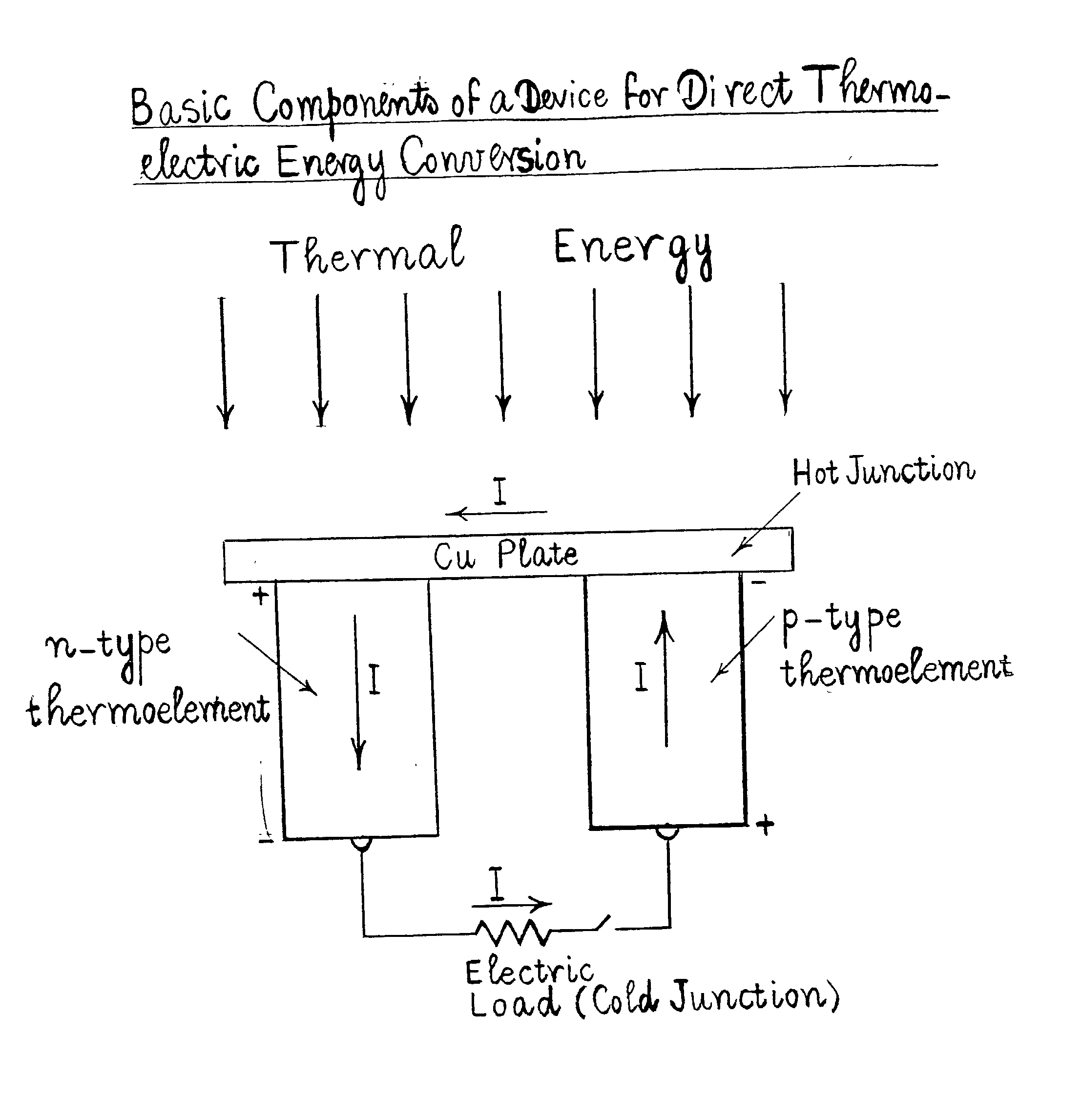
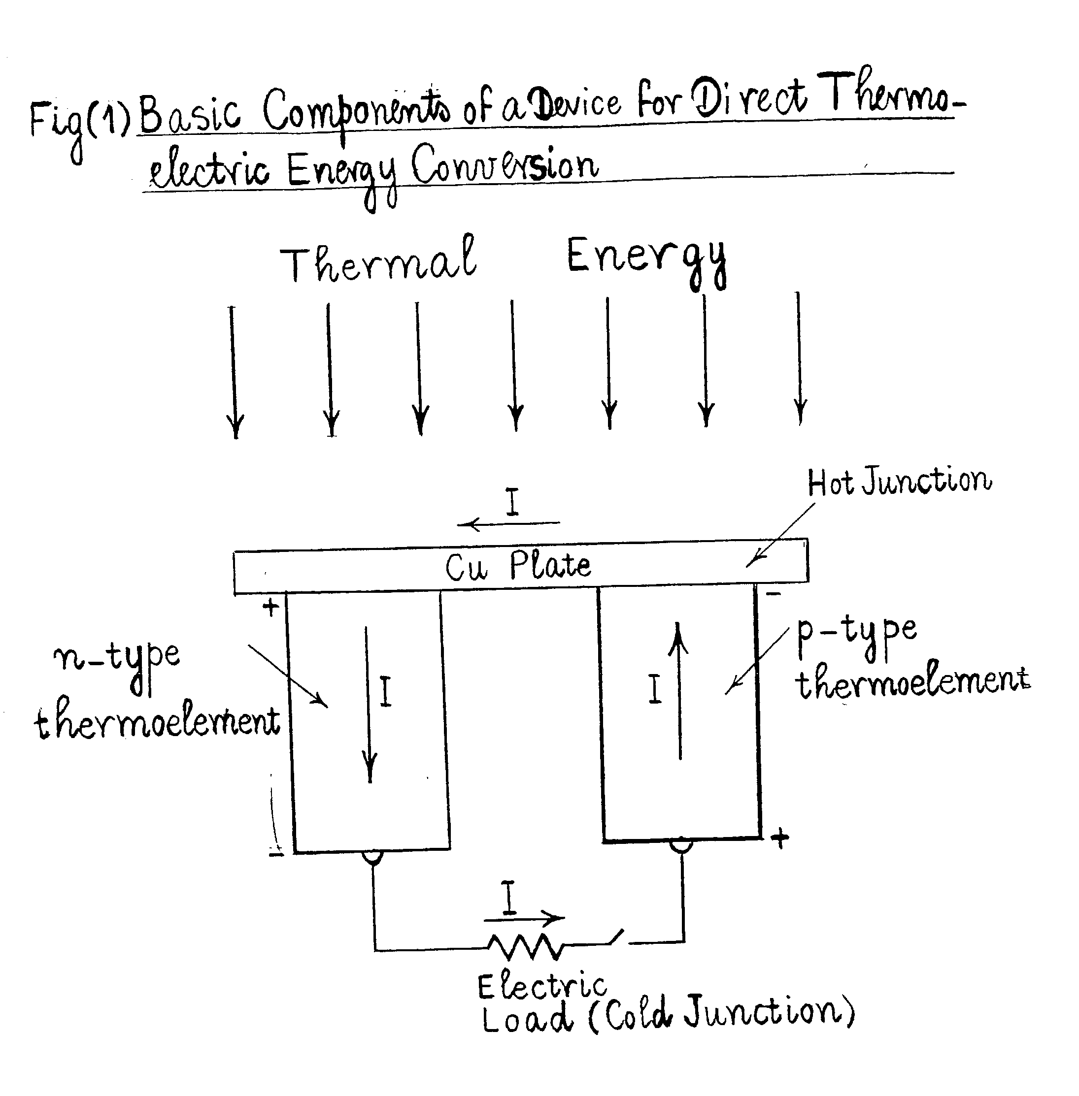
Method for producing a device for direct thermoelectric energy conversion
a technology of thermoelectric energy conversion and production method, which is applied in the direction of thermoelectric device junction materials, crystal growth processes, electrical apparatus, etc., can solve the problems of brittleness, temperature dependent properties and lack of chemical stability, energy conversion efficiency, and heat absorbed, and achieves the effects of less than those of metals
- Summary
- Abstract
- Description
- Claims
- Application Information
AI Technical Summary
Problems solved by technology
Method used
Image

Examples
first embodiment
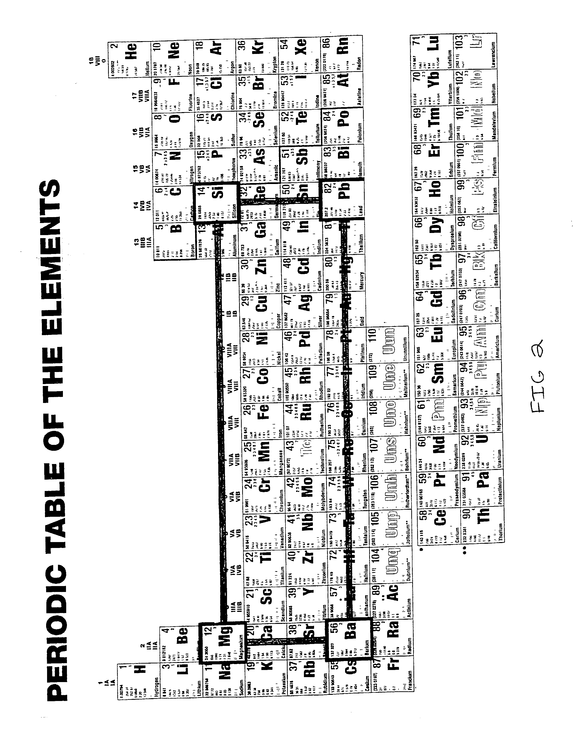
[0040] According to another embodiment or aspect of this invention, the additional doping materials for the n-type branch of the device, as defined in the preceding first embodiment, comprise one, or more, elements, selected from the group consisting of nitrogen, phosphorus, arsenic, antimony, bismuth, oxygen, sulfur, selenium, tellurium, chlorine, bromine, iodine, magnesium, barium, lithium, gold, aluminum, indium, iron and / or compounds thereof.
[0041] According to another embodiment or aspect of this invention, the additional doping materials, for the p-type branch of the device, as defined in the preceding first embodiment, comprise one, or more, elements, selected from the group consisting of copper, silver, sodium, potassium, rubidium, cesium, boron, silicon, lead and / or compounds thereof.
[0042] According to another embodiment or aspect of this invention, as defined in the preceding three embodiments, r varies from 0.1 to 0.4, (1-r) varies from 0.6 to 0.9, x varies from 0.1 to 0...
seventh embodiment
[0050] According to another embodiment or aspect of this invention, the additional doping material, or materials, for the p-type branch of the device, in the preceding seventh embodiment, comprise one, or more, elements, selected from the group consisting of copper, silver, sodium, potassium, rubidium, cesium, boron, silicon, lead and / or one, or more, of the compounds of these elements.
[0051] According to another embodiment or aspect of this invention, in the foregoing three embodiments, r varies from 0.1 to 0.4, (1-r) varies from 0.6 to 0.9, each of u, v and w varies from 0 to 0.3, (u+v+w) varies from 0 to 0.3, z is not less than 0.1, s varies from 0.1 to 0.3, (1-s) varies from 0.7 to 0.9, each of a, b, d, e, f and g varies from 0 to 0.2, (a+b+d+e+f+g) varies from 0 to 0.2, c is not less than 0.1, the atomic, or molecular, proportion of the doping material, or materials, in the alloy varies from 10.sup.-8 to 10.sup.-1 and the free charge carrier concentration varies from 1.times.10...
PUM
| Property | Measurement | Unit |
|---|---|---|
| Pressure | aaaaa | aaaaa |
| Pressure | aaaaa | aaaaa |
| Pressure | aaaaa | aaaaa |
Abstract
Description
Claims
Application Information