
Retractable rotary turret

a rotary turret and rotor technology, applied in the field of rotor rotors, can solve the problems of inability to use storage bays for other components, inability to match output beams, and generally insufficient operation of on-axis telescope configuration, so as to reduce the dead space in the deployment vehicle, maximize the volume available for other components, and reduce the deployment time

Active Publication Date: 2014-01-28
RAYTHEON CO
View PDF52 Cites 25 Cited by
  • Summary
  • Abstract
  • Description
  • Claims
  • Application Information

AI Technical Summary

Benefits of technology

The technology described in this patent allows for a turret system to be rotated along a single dimension for deployment, reducing the need for translation of the azimuth base and decreasing deployment time. The use of conformal apertures also helps to ensure a consistent spherical shape in the airflow around the deployment vehicle, maximizing the correction of aero-optic wavefront error and torque disturbances on the outer parts of the turret system. Additionally, the technology allows for the reduction of large, low order wavefront aberrations and residual tilts of the high power laser beam.

Problems solved by technology

With these mechanisms the storage bay volume is empty during system deployment, but the storage bay cannot be used for other components due to the need of the space during system retraction.
However, a central obscuration created by a secondary mirror results in a matching hole in the output beam.
The on-axis telescope configuration, generally, does not operate correctly for beam systems that produce a solid beam profile with no central obscuration.

Method used


Image

  • Retractable rotary turret
  • Retractable rotary turret
  • Retractable rotary turret

Examples


Embodiment Construction

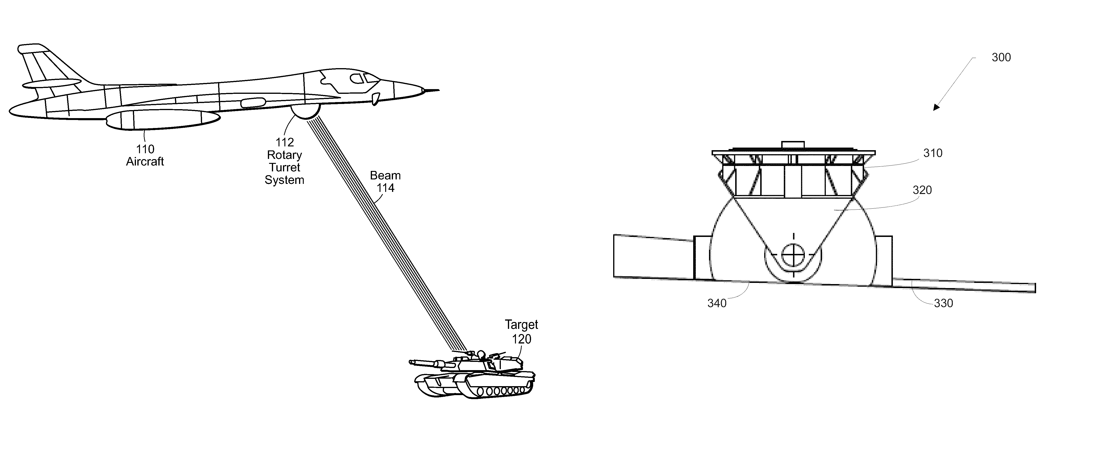
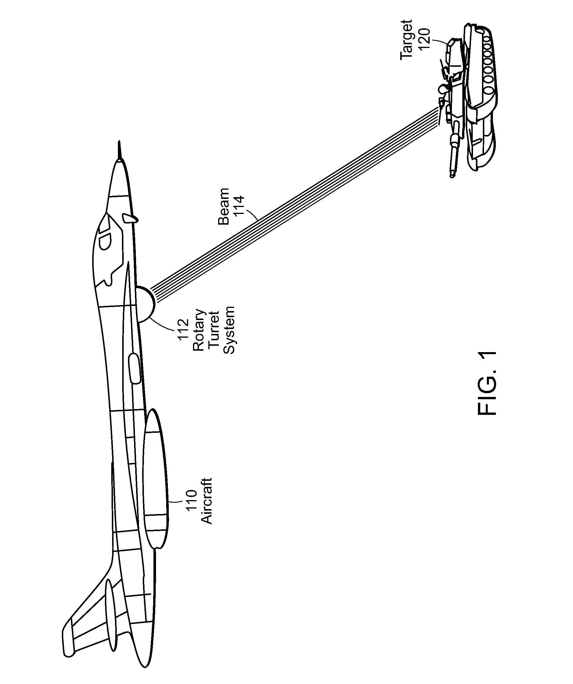
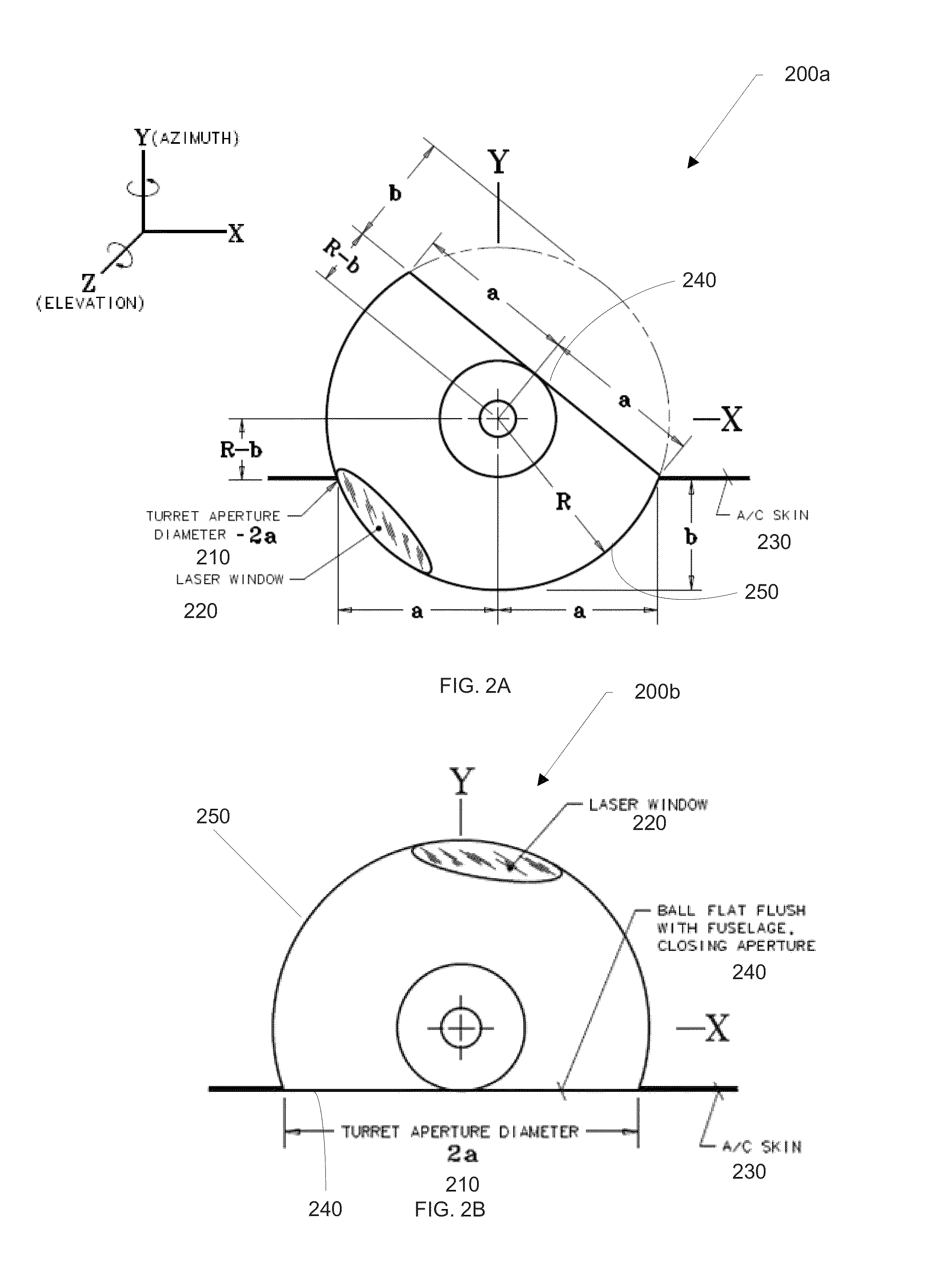
[0051]A retractable rotary turret and / or rapidly deployable high energy laser beam delivery system includes technology that, generally, provides a rapidly deployable turret system (e.g., a truncated sphere, a rounded protrusion, a rotating platform, etc.) that can be used with a deployment vehicle (e.g., low observability aircraft, aircraft, tank, helicopter, etc.) for delivery of a beam. The technology for rapid deployment of the mechanisms can be utilized to deliver the beam (e.g., laser beam, light beam, sensor beam, etc.) to a target. The technology enables sensitive components of the beam delivery system (e.g., sensor, telescope, window, etc.) to be protected during selected movements by the deployment vehicle (e.g., take-off and / or landing of an aircraft, movement of a tank through a forest, etc.) and rapidly deployed for beam delivery (e.g., two second deployment, etc.).

[0052]The technology can provide for deployment via a rotary motion of the turret system. The technology el...


PUM


Abstract

The technology can include a retractable rotary turret system. The system includes a base comprising two support arms. The system further includes a turret platform that is a truncated sphere having a substantially flat side and a substantially spherical side. The turret platform includes a turret support ring rotary coupled to the two support arms and a turret device isolatively coupled to the turret support ring. The turret platform is rotatable along a first dimension for deployment of the spherical side and is rotatable along the first dimension for deployment of the flat side.

Description

BACKGROUND[0001]Beam delivery systems (e.g., sensor beam, laser beam, etc.) have generally been mounted in pods on the exterior of an aircraft, such as an unmanned aerial vehicle, a helicopter, or a fixed wing aircraft. Stowing mechanisms and features are generally used on the pod to protect the primary windows of the beam delivery system during take-off and landing of the aircraft. The pod itself generally remains outside the aircraft in the windstream. Typically, when the entire system must be protected, deployment mechanisms are used to move the turret from a storage bay of the aircraft into the windstream. With these mechanisms the storage bay volume is empty during system deployment, but the storage bay cannot be used for other components due to the need of the space during system retraction. In other configurations of the system, the predominant axis is roll, with azimuth and elevation gimbals nestled within the roll windscreen. In these configurations, the forward look angle ...

Claims


Application Information

Patent Timeline
Patent Type & Authority Patents(United States)
IPC IPC(8): F41A23/24
CPCF41A23/20F41H13/005
Inventor KING, WILLIAM B.ISKER, JOHN D.MCKEARN, CHAUNCHY F.GRIFFIN, ERIC J.
Owner RAYTHEON CO
Learn More