
Matched precipitation rate rotor-type sprinkler with selectable nozzle ports

Active Publication Date: 2014-01-28
HUNTER INDUSTRIES
View PDF19 Cites 12 Cited by
  • Summary
  • Abstract
  • Description
  • Claims
  • Application Information

AI Technical Summary

Benefits of technology

The present invention is an irrigation sprinkler that can rotate and has two ports for emitting water. It also has a diverter valve that can change the flow of water between the two ports as the nozzle rotates. The sprinkler has a gear train reduction and a turbine that is rotated by water flowing through the riser. The technical effect of this invention is that it allows for more efficient and precise irrigation.

Problems solved by technology

Many parts of the world lack sufficient rainfall at different times of the year to maintain the health of turf and landscaping.
Unfortunately rotor-type sprinklers do not typically irrigate a given area with matched precipitation rates.
Thus, the rotor-type sprinklers that are set for a smaller arc may over-water the areas watered by those sprinklers, resulting in a substantial waste of water.
This configuration of an irrigation system requires more underground pipes and complex programming of the irrigation controller.
However, rotary stream sprinklers have a limited range or radius and are not suitable for use when large areas of landscape must be watered such as golf courses and playing fields.
This requires that the installer possess a high level of skill and adds undue complexity to the irrigation system.
Moreover, it is not practical to supply a large selection of nozzles having different flow rates to match, for example, the precipitation from a rotor-type sprinkler set to water over an arc of one hundred and twenty degrees to a rotor-type sprinkler set to water an arc of two hundred and seventy degrees.

Method used


Image

  • Matched precipitation rate rotor-type sprinkler with selectable nozzle ports
  • Matched precipitation rate rotor-type sprinkler with selectable nozzle ports
  • Matched precipitation rate rotor-type sprinkler with selectable nozzle ports

Examples


embodiment 30

[0083]FIGS. 19 and 20A-20C illustrate a first alternate embodiment 30′ of the sprinkler that causes both the high flow rate port 56a and the low flow rate port 56b to be open at the same time. In this embodiment, each of a plurality of cams 200 has two cam surfaces formed by two overlapping vertical triangles. A shorter outermost surface 202 causes the high flow rate port 56a to be completely blocked and water to flow through the low flow rate port 56b as seen in FIG. 20B. When the cam follower 96 is in contact with an innermost taller surface 204, the diverter valve member 88 is positioned to cause water to flow through both the low flow rate port 56b and the high flow rate port 56a at the same time (FIGS. 19 and 20C). When the cam follower 96 is not contacting either surface of the cam 200, all of the water can flow through the high flow rate port 56a as illustrated in FIG. 20A. This feature may be important when the low flow rate port 56b sends water to a different radius for the...

first embodiment

[0095]The cams 398 (FIG. 39) have different cam surfaces to position the diverter valve member 388 in different orientations. An outer cam surface 402 (FIG. 30A) is the outermost cam surface and causes the high flow rate port 356a to be completely blocked and water to flow through the low flow rate port 356b as illustrated in FIG. 41. The cams 398 also include a mid-cam surface 404 (FIG. 30A). When the cam follower 396 engages the mid-cam 404 surface, the diverter valve member 388 is positioned to cause a limited flow of water to flow through the low flow rate port 356b and a full flow of water through the high flow rate port 356a as illustrated in FIG. 38 The cams 398 also include an inner cam surface 406 (FIG. 30A). When the cam follower 396 engages the inner cam surface 406, the diverter valve member 388 is positioned to allow maximum water flow through both the low flow rate port 356b and the high flow rate port 356a at the same time (FIG. 32). Alternatively, the cams may only h...


PUM


Abstract

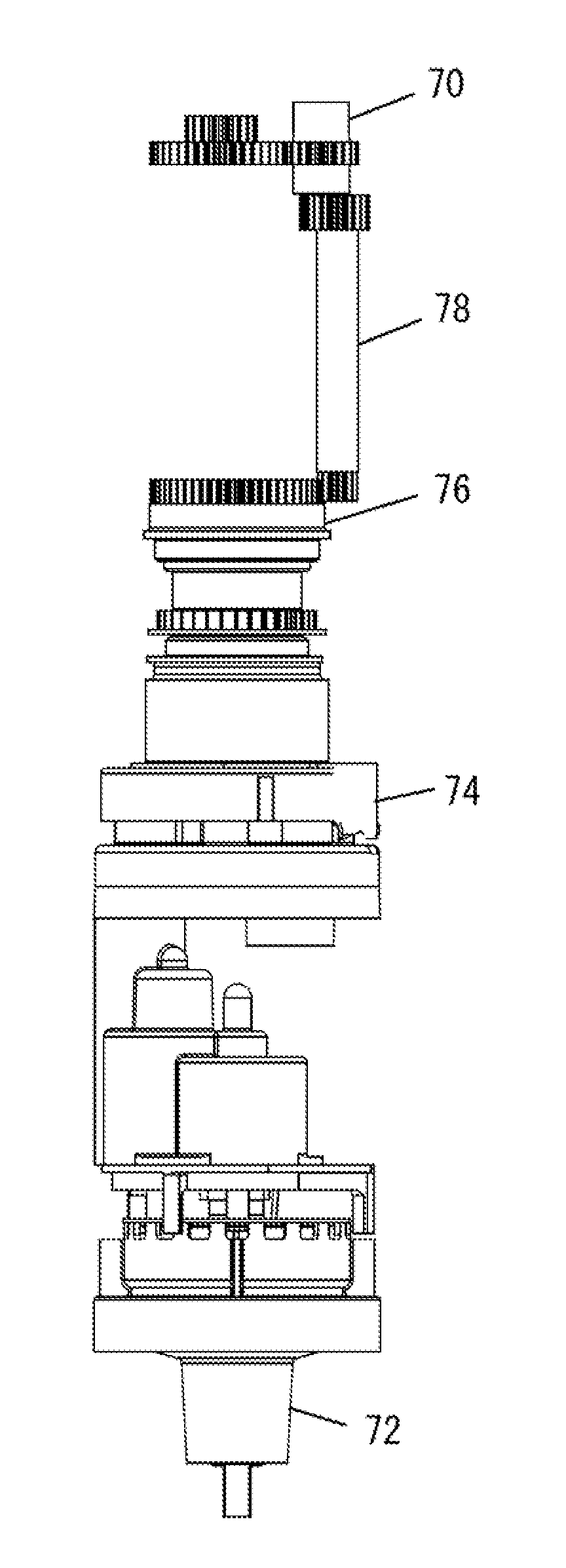
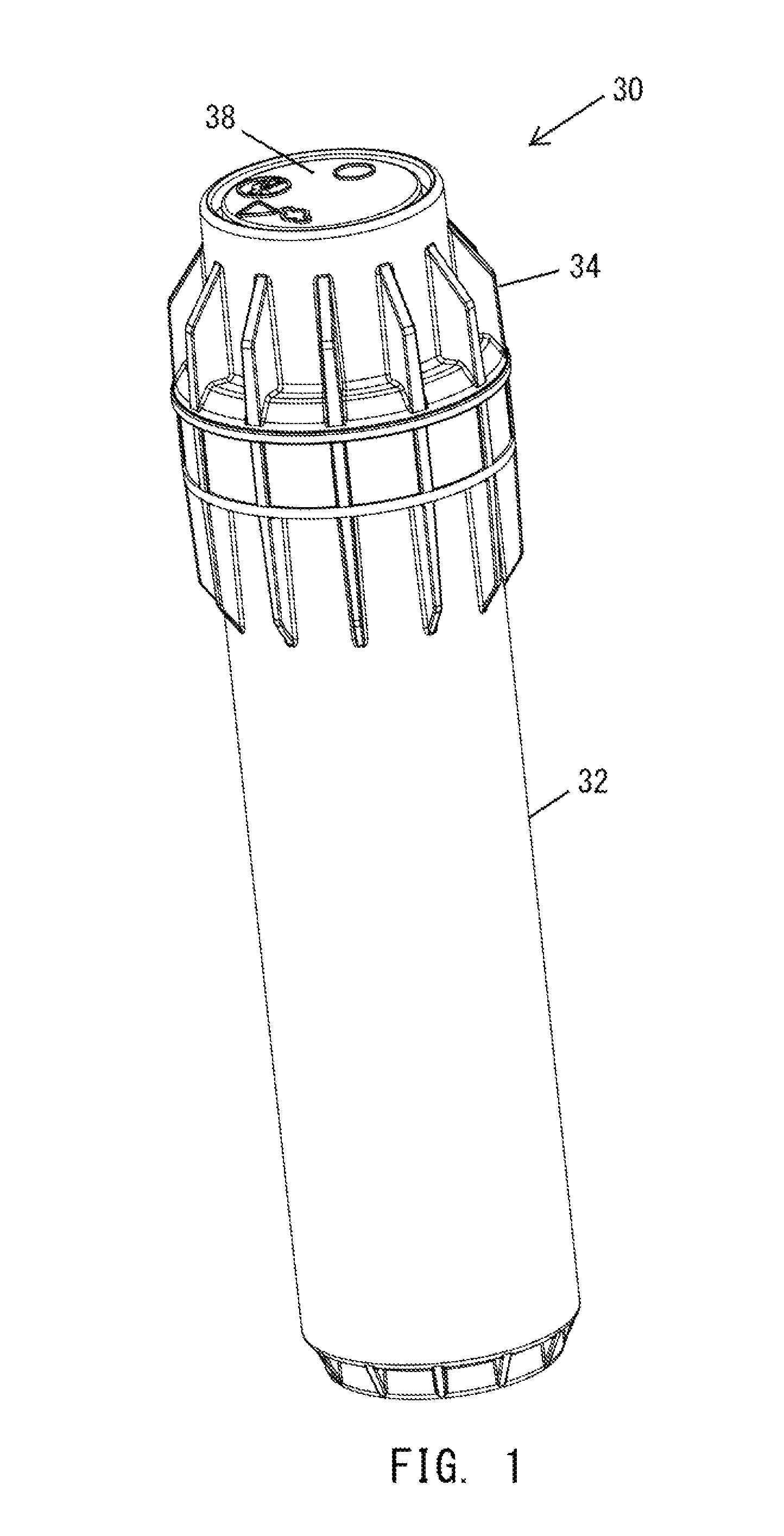
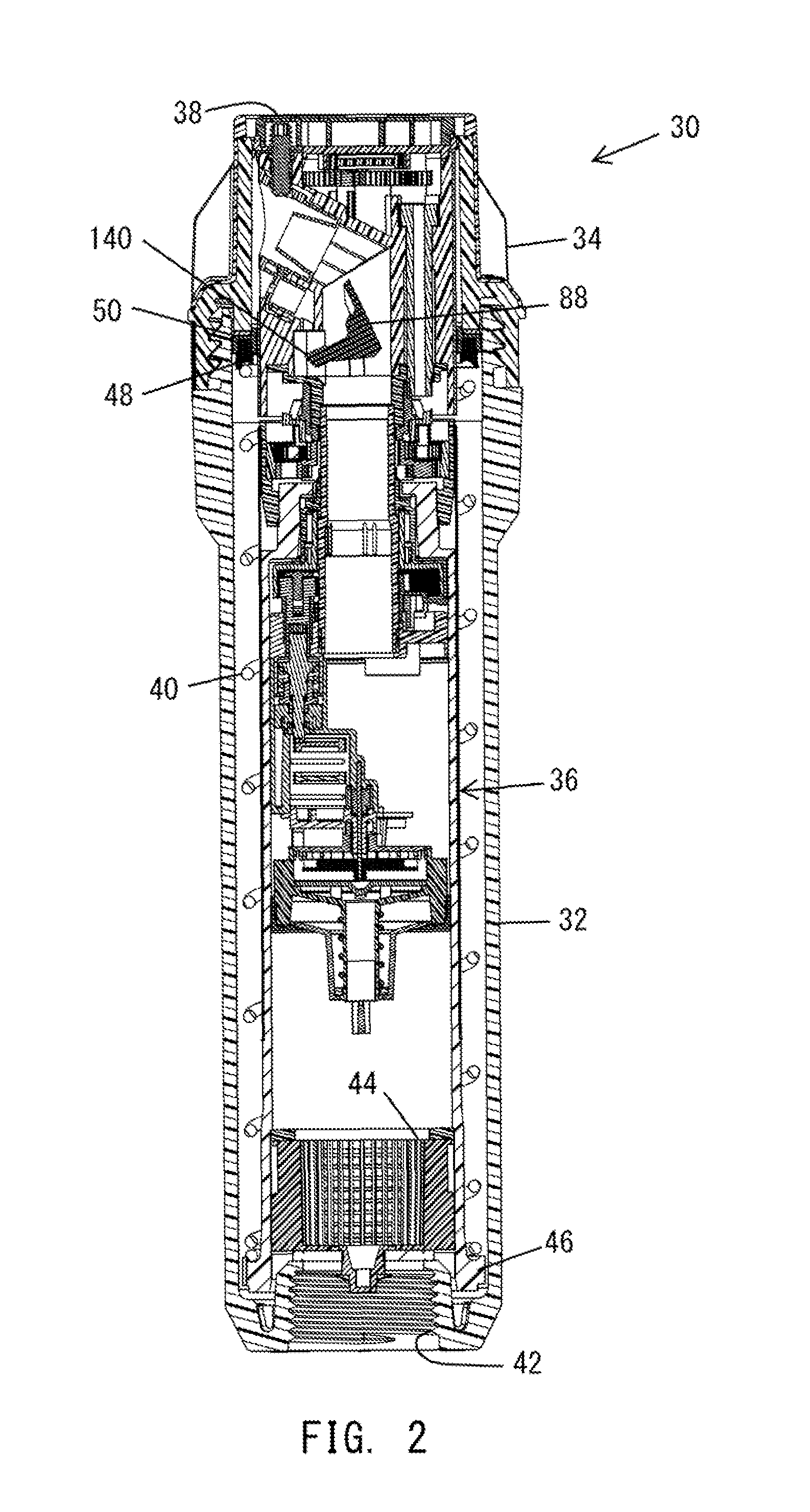
An irrigation sprinkler includes a riser and a nozzle mounted at an upper end of the riser for rotation and configured with a high flow rate port and a low flow rate port that can each emit a stream of water from a high flow rate nozzle port and a low flow rate nozzle port. The sprinkler further includes a diverter valve that can intermittently shift the flow of water between the high flow rate port and the low flow rate port as the nozzle rotates. The sprinkler also includes a gear train reduction mounted in the riser and coupled to rotate the nozzle. A turbine is coupled to an input shaft of the gear train reduction and is rotatable by water flowing through the riser.

Description

CROSS-REFERENCE TO RELATED APPLICATION[0001]This application claims priority under 35 U.S.C. Sections 119 and 120 based on the filing date of the similarly entitled U.S. Provisional Patent Application Ser. No. 61 / 371,099 filed by Michael L. Clark et al. on Aug. 5, 2010 and assigned to Hunter Industries, Inc., the assignee of the subject utility patent application. The entire disclosure of the aforementioned provisional application is hereby incorporated by reference.FIELD OF THE INVENTION[0002]The present invention relates to sprinklers used in residential and commercial irrigation for watering turf and landscaping.BACKGROUND OF THE INVENTION[0003]Many parts of the world lack sufficient rainfall at different times of the year to maintain the health of turf and landscaping. Irrigation systems are therefore used to deliver water to such vegetation from municipal water supplies and wells according to a watering schedule. A typical irrigation system comprises a programmable controller t...

Claims


Application Information

Patent Timeline
IPC IPC(8): B05B3/16
CPCB05B3/0431B05B15/10B05B3/16B05B15/74
Inventor CLARK, MICHAEL L.SHEETZ, III, DONALD M.PORTER, LAMONTE D.
Owner HUNTER INDUSTRIES
Learn More