Crawler travel unit

a travel unit and crawler technology, applied in the direction of gearing, belt/chain/gearing, tractors, etc., can solve the problems of large rearmost idling wheel, and the inability to support the load, so as to suppress the lifting of the pivot shaft, reduce the vertical vibration of the track frame, and suppress the effect of the pivot shaft lifting

Active Publication Date: 2014-01-28
KUBOTA LTD
View PDF29 Cites 8 Cited by
  • Summary
  • Abstract
  • Description
  • Claims
  • Application Information

AI Technical Summary

Benefits of technology

[0019]The crawler travel unit having the above-mentioned configurations has the following effects.
[0020]For example, when the idling wheel on the front side runs on an obstacle M, such as stone, two idling wheels on the rear side each pivoted on the first rocking link are brought into contact with the ground at the same time due to the swing of the rocking link, and therefore, the load on the rear portion of the track frame is shared by the two idling wheels on the rear side, and the load on the idling wheel on the front side can be reduced as well.
[0021]In addition, when the idling wheel on the front side of the two rear idling wheels runs on an obstacle, the rearmost idling wheel is lowered due to the seesaw-like swing of the rocking link, which suppresses the lifting of the pivot shaft of the rocking link, and then suppresses vibration of the track frame.
[0022]According to the present invention, when the idling wheel on the front side runs on an obstacle, such as stone, two idling wheels on the rear side are brought into contact with the ground at the same time due to the swing of the rocking link, and therefore, the load is shared by the two idling wheels on the rear side. The load on the idling wheel on the front side, in addition to the load on the idling wheel on the rear side, can be reduced as well, and vertical vibration of the track frame can be reduced.

Problems solved by technology

However, when front and rear idling wheels run on obstacles, such as stones, an intermediate idling wheel may be lifted and cannot support the load, i.e., the entire load is supported solely by the two (front and rear) idling wheels.
Especially, in a case where a load is on a rear portion of the track frame, when the front idling wheel runs on an obstacle, such as stone, a load on the rearmost idling wheel becomes excessive, leading to larger vertical vibration of the track frame.

Method used


Image

  • Crawler travel unit
  • Crawler travel unit
  • Crawler travel unit

Examples


example 1

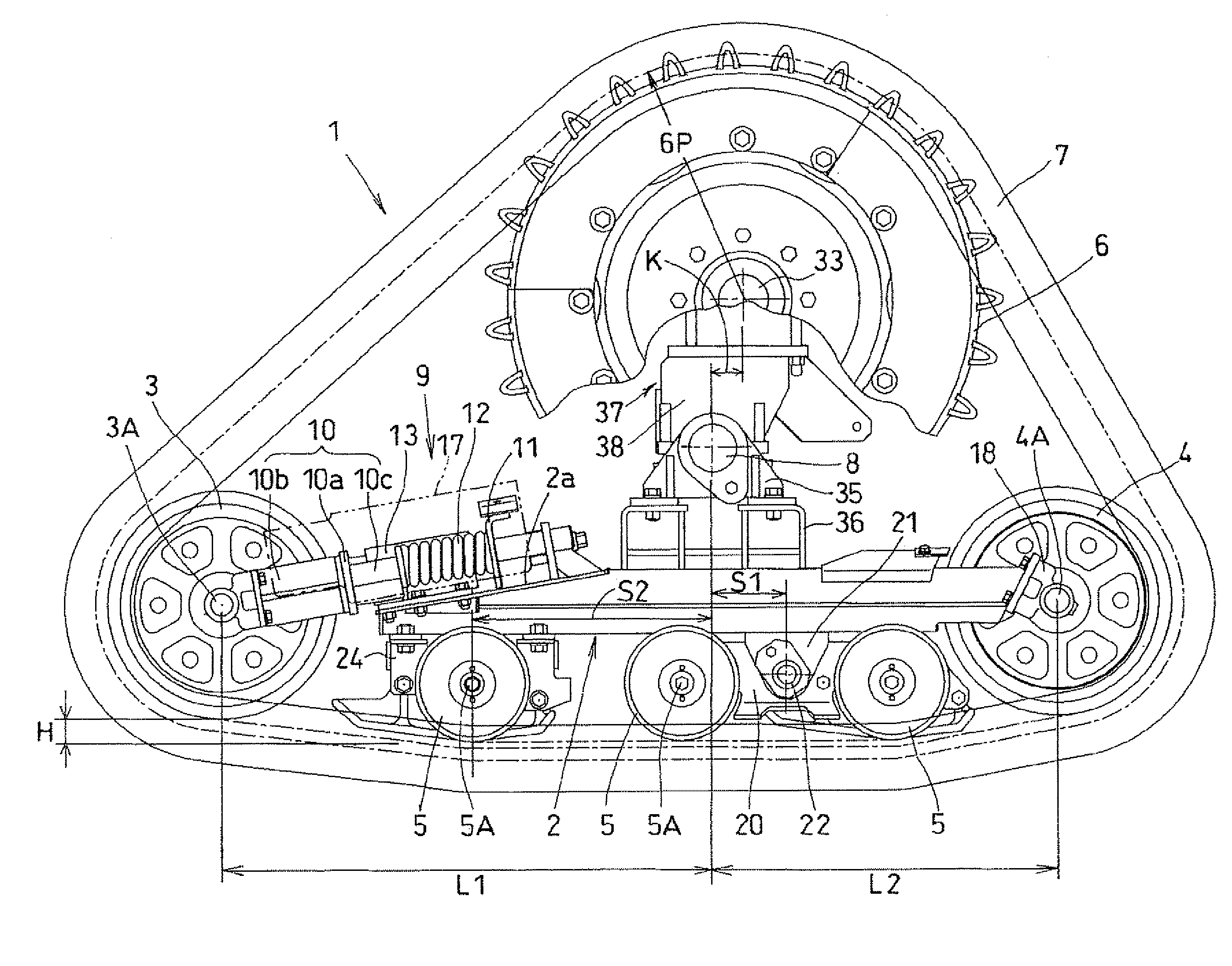
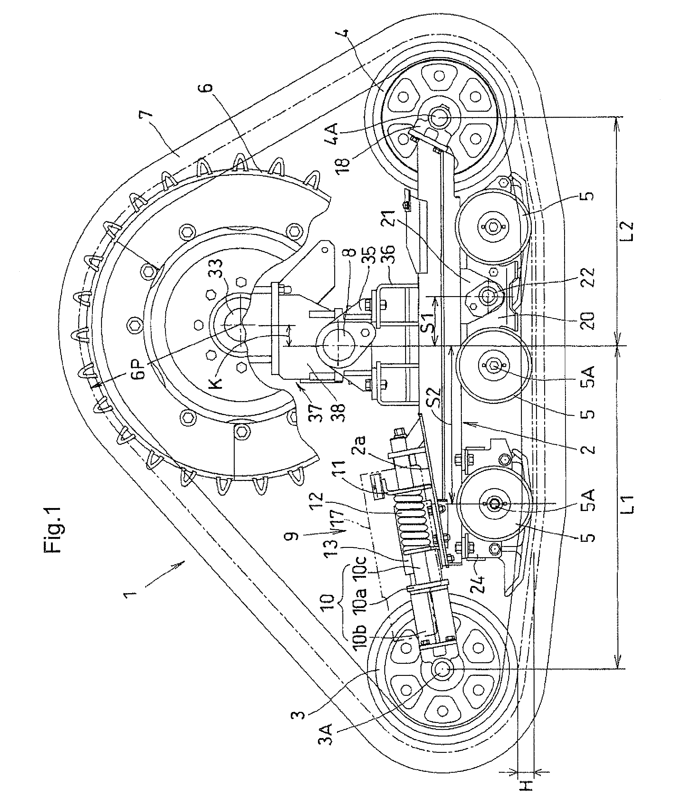
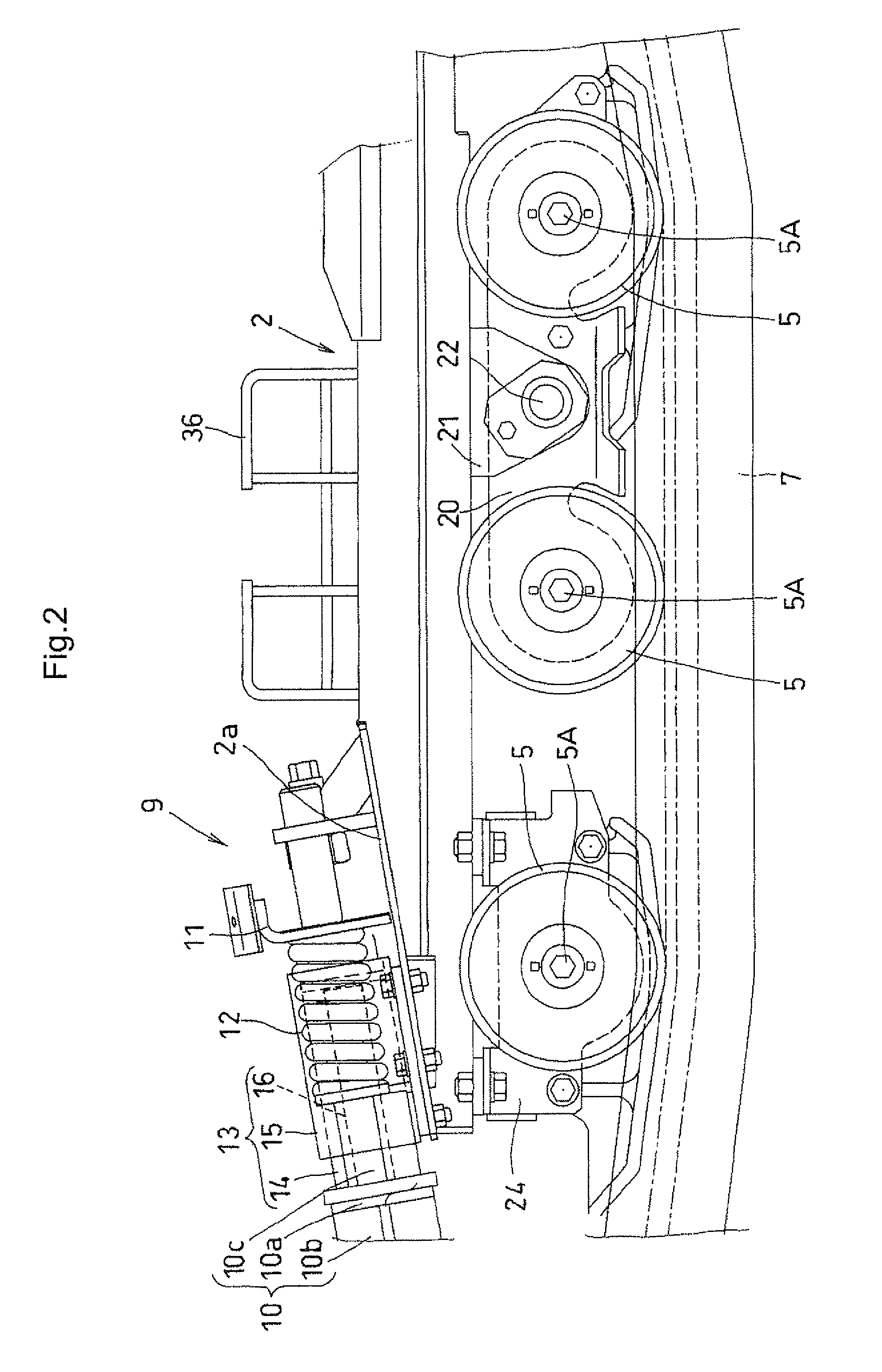
[0032]FIGS. 1 to 5 and 7 illustrate a first embodiment. In FIG. 7, an entire tractor T is shown. The tractor T with a crawler travel unit 1 has a travel machine body 30. The travel machine body 30 includes an engine E, a transmission case 31, a front axle frame (not shown) and the like. The tractor T has a front wheel as a steering control wheel which can be power-driven, attached to the front axle frame. The engine is covered with a bonnet, and an operation part and a driver's seat are held in a cabin or ROPS. In a rear portion of the travel machine body 30, a rear working machine (implement), such as a rotary cultivator, is towed or supported through a hydraulic pressure device and a three-point link mechanism (H). Hereinbelow, the descriptions will be made with reference to the drawings showing a left side of the crawler travel unit 1, but the corresponding members are similarly arranged on a right side of the crawler travel unit 1.

[0033]The crawler travel unit 1 has: a track fra...


PUM


Abstract

A track frame is swingably supported by a rear axle case of a travel machine body through a rocking shaft; front and rear driven wheels are disposed in front and rear end portions of the track frame; at least three idling wheels are disposed on an intermediate portion of the track frame at intervals in a longitudinal direction; a drive wheel which is disposed upward of a longitudinal intermediate portion of the track frame and is configured to receive a power transmitted from a rear axle supported by the rear axle case; and a crawler belt is wrapped around the drive wheel, the front driven wheel, the rear driven wheel and the idling wheels. Two idling wheels on a rear side of the at least three idling wheels are pivoted on a first rocking link, and a longitudinal intermediate portion of the first rocking link is pivoted on the track frame through a first pivot shaft.

Description

BACKGROUND OF THE INVENTION[0001]1. Field of the Invention[0002]The present invention relates to a crawler travel unit mountable on a rear portion of a tractor or the like.[0003]2. Description of Related Art[0004]As a crawler travel unit, there can be mentioned those used in a semi-crawler tractor, in which the unit is installed as a rear wheel tire of the tractor, or replaceable with a rear wheel tire.[0005]In the prior art of the crawler travel unit of this type, for example, as disclosed in Patent document 1, a front driven wheel for adjusting tension, a driven wheel which loosely rotates and idling wheels therebetween are aligned in a front-rear direction and supported by a track frame; a drive wheel is arranged upward of the idling wheels; a crawler track is wrapped around all of these wheels; a tension adjusting mechanism for supporting the front driven wheel and biasing the same in a direction that adjusts tension is sloping downward from the track frame to the front driven w...

Claims


Application Information

Patent Timeline
Patent Type & Authority Patents(United States)
IPC IPC(8): B62D55/14B62D55/084
CPCB62D55/084B62D55/14B62D55/15B62D49/0635B62D55/30B62D55/08B62D55/10B62D55/18
Inventor INAOKA, MOTONARI
Owner KUBOTA LTD
Why Eureka
Try Eureka