Supercharge Your Innovation With Domain-Expert AI Agents!

Multi-purpose reacher-grabber tool

a multi-purpose, reacher-grabber technology, applied in the field of multi-purpose reacher-grabber tools, can solve the problems of inability to interchange or extend the pole, inconvenient use, and inability to grip the pole, etc., and achieve the effect of reducing width and widening width

Active Publication Date: 2014-02-04
PERRY SPECIALTY PROD CO LLC
View PDF17 Cites 9 Cited by
  • Summary
  • Abstract
  • Description
  • Claims
  • Application Information

AI Technical Summary

Benefits of technology

The present invention is about a multi-purpose reacher-grabber tool that has two interconnected appendages extending in two different directions from an end of an interchangeable extension pole. The tool can be used in a close tolerance environment without moving parts and can grip pull-cords, pull-chains, and the like. It can operate at more than one angle and can be operated with one hand. The tool doesn't require a manual squeezing or rope-pulling action and can be operated without a stop button on the pull-cord. The tool can be used to operate window shutters or other objects with internal Acme threads to attach it to existing poles.

Problems solved by technology

This conventional form of reacher-grabber tool has limitations for the user with weak finger muscles or no gripping capability.
Such prior tools have some or all of the following disadvantages:The reach of the tool is fixed by the length of the operator linkage to the grasping apparatus, making interchangeable or extendable poles impractical.
This lack of extendability means a ladder is needed by the operator for very high and very low distances.The clamping appendages must be manipulated into an open position before being able to grasp or hook the work object, thus requiring additional space to perform the action.Lacks capability to adjust plantation style window shutter louvers.Lacks capability to lock some types of objects into the tool including pull-chains positioned at any angle as well as wire and cord with or without a pull-button for manipulation.Clamping fingers require an opposed moving finger to grasp a work object.
A single finger cannot clamp or grasp the work object independently.The contact mechanism provides only one suitable engagement angle, so only one approach angle is available.Operating two movable handle pieces or devices makes it difficult to rotate the tool 360 degrees in either direction with one hand.Multi-purpose functionality for additional tasks such as scraping is not facilitated.The force used to retrieve or manipulate an object once contact is made is left to the operator's hand squeezing strength on the trigger or handles to provide the necessary force to retain the object within the clamping appendages.No part stops insertion of an appendage at a specific distance relative to a work object such as a louver for opening and closing the louver on one side of its pivot axis.

Method used


Image

  • Multi-purpose reacher-grabber tool
  • Multi-purpose reacher-grabber tool
  • Multi-purpose reacher-grabber tool

Examples


embodiment 30

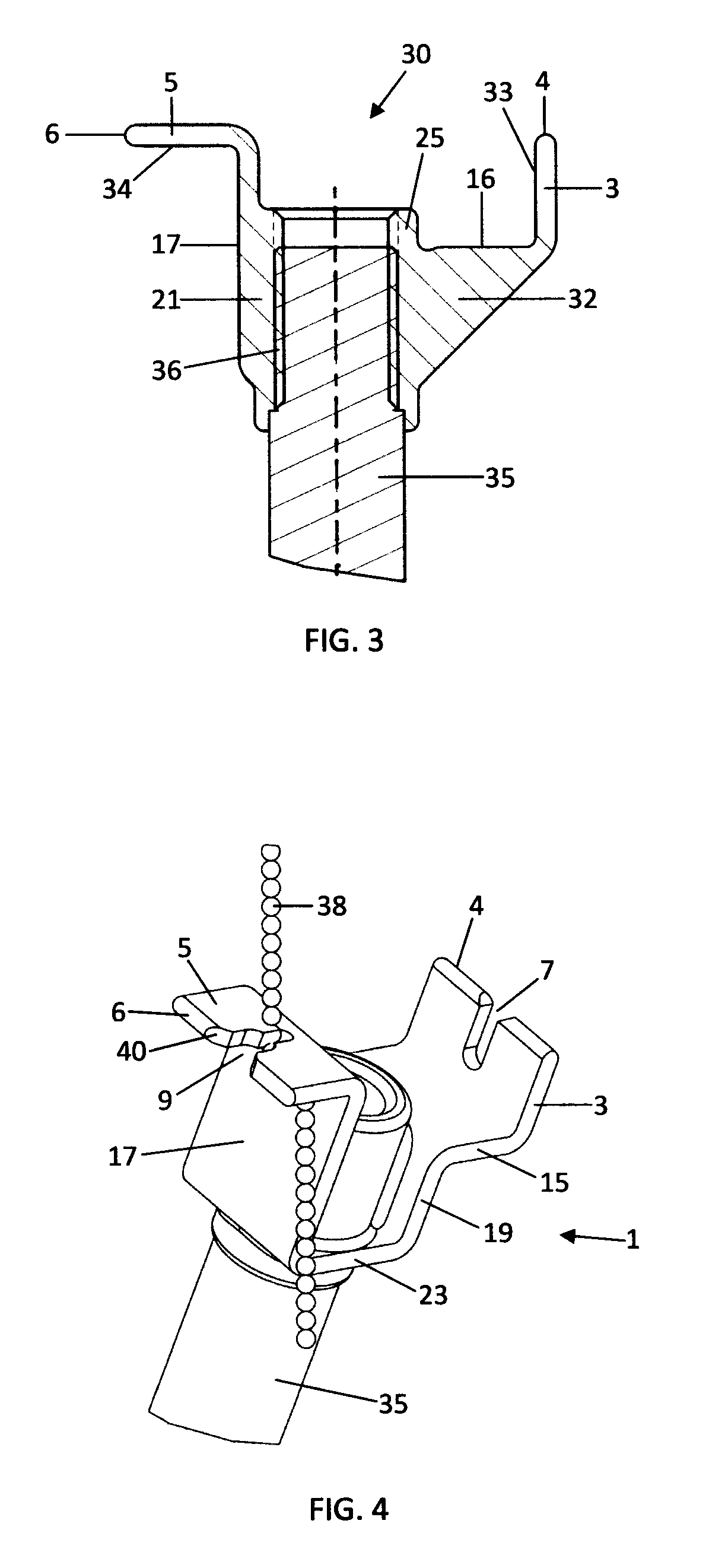
[0027]FIG. 3 is a sectional view of an embodiment 30 the invention having a diagonal brace 32. A hooking surface 33 on the first appendage 3 may be used for manipulations such as hooking and lifting. A hooking surface 34 on the second appendage 5 may be used for manipulations such as hooking, pulling, and lifting. Open-ended slots, not shown in this figure, may be provided as previously shown. The tool may be connected to a pole 35 by a threaded connection 36. Standard Acme internal threads may be provided in the pole-connection mechanism 25, so that common extension poles may be used interchangeably, such as a mop handle, a paint roller extension pole, and the like, depending on the reach distance needed.

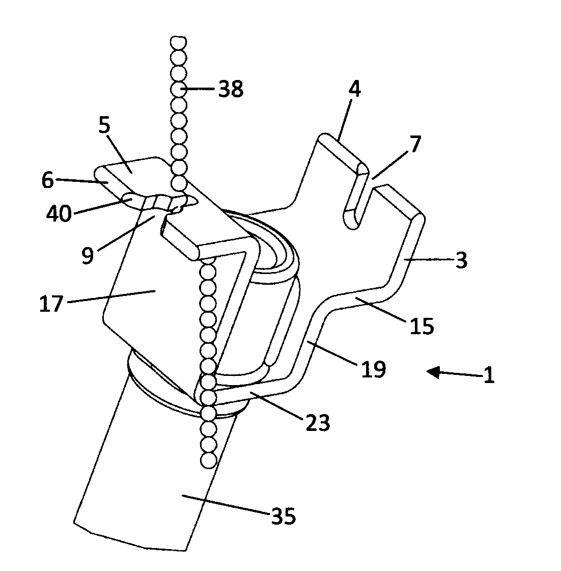
[0028]FIG. 4 illustrates the tool 1 being used to manipulate a flexible beaded chain 38 using the graduated open-ended slot 9, 11, 13 previously described. The chain 38 may be guided into the slot by object feeder chamfers 40 at the distal corners of the open-ended slot 9. It may t...

embodiment 50

[0031]FIG. 5 illustrates and embodiment 50 two removable soft sleeve covers 42 on the appendages 3 and 5. These covers 42 may be made of a softer material than the appendages, such as vinyl. They may be used on any embodiment shown herein. They protect the work object from scratches when the open-ended slots are not needed, such as for pushing or pulling an edge of a window louver to open or close it. FIG. 5 also shows the tool formed from a flat bar with a central U-shaped portion 19, 21, 23 serving as a wrench on a flat-sided nut 52.

Operation

[0032]Soft sleeve covers 42 may be placed on one or both appendages as needed for protection of the work object finish and for improved surface friction on the work object. The covers 42 can be removed for functions that use the appendage edges or surfaces and / or the open-ended slots 7 and 9. Sliding glass door tracks can be cleaned by sliding a cloth in the tracks with the tool. The first or second appendage may be used to push the cloth to t...


PUM


Abstract

A tool with two interconnected appendages extending in two different directions from an end of an interchangeable extension pole. The first appendage may be oriented along a plane substantially parallel to the pole axis. The second appendage may be oriented along a plane substantially normal to the axis. An open-ended slot may be provided in each appendage for grabbing cords and other items. At least one of the open-ended slots may graduate from a larger width at an open end of the slot to a reduced width toward a closed end of the slot. Pull-chains to be operated can be inserted and locked into the smaller portion of the slot. Stop surfaces may be provided that limit insertion of an appendage to a specific distance, for example to operate a louver of a window shutter. Internal Acme threads may be provided in the tool to attach it to existing poles.

Description

CROSS-REFERENCES TO RELATED APPLICATIONS[0001]This application claims the priority benefit of pending provisional patent application 61 / 527,665, filed on Aug. 26, 2011.FIELD OF THE INVENTION[0002]The invention relates to multi-purpose reacher-grabber tools offering functionality to reach and manipulate hard-to-reach objects.BACKGROUND[0003]Various types of reacher-grabber tools are known in the prior art. Examples are found in U.S. Pat. No. 8,091,936 issued to Graziano on January 2011; U.S. Pat. No. 4,613,179 issued to van Zelm on September 1986; U.S. Pat. No. 4,441,746 issued to Corboy, Jr. on April 1984; U.S. Pat. No. 5,823,590 issued to Forrest on October 1998, and U.S. Pat. No. 6,467,823 issued to Brekken on October 2002.[0004]Prior reacher-grabber tools provide clamping appendages with gripping ends that extend from an end of a pole. The appendages open and close by squeezing a spring handle style trigger or pulling a rope at the opposite end of the pole. This conventional form...

Claims


Application Information

Patent Timeline
IPC IPC(8): A47F13/06
CPCA47F13/06
Inventor PERRY, DOUGLAS, D.
Owner PERRY SPECIALTY PROD CO LLC
Features
  • R&D
  • Intellectual Property
  • Life Sciences
  • Materials
  • Tech Scout
  • Unparalleled Data Quality
  • Higher Quality Content
  • 60% Fewer Hallucinations
Learn More