
Engine driven vehicle with transmission

a transmission and engine technology, applied in the field of motor vehicles, can solve the problems of reducing the accuracy of implementing a predetermined gear change strategy, difficult automatic transmission control, etc., and achieve the effects of less engine load, reliable gear selection, and increased comfort of the driver

Active Publication Date: 2014-02-04
VOLVO LASTVAGNAR AB
View PDF19 Cites 2 Cited by
  • Summary
  • Abstract
  • Description
  • Claims
  • Application Information

AI Technical Summary

Benefits of technology

The patent is about a system that helps drivers in vehicles with automatic gearboxes choose the best gear based on factors like fuel efficiency or average speed. This is done by using existing components and sensors in the vehicle to get more accurate information about its resistance to travel. The system also improves the vehicle's performance by making better gear selections and reducing wear and tear on the transmission. This approach is cost-effective and improves driving comfort. Overall, the system helps drivers choose the best gear for the situation they are in, which can save money, make driving easier, and improve vehicle performance.

Problems solved by technology

A disadvantage of the known technology is the difficulty of controlling the transmission automatically when the vehicle is being driven in changing environments.
For example, the weather can cause changes in the characteristics of the surface on which the vehicle is being driven, or the vehicle's speed or external wind can cause a reduction in the accuracy in implementing a predetermined gear change strategy.

Method used


Image

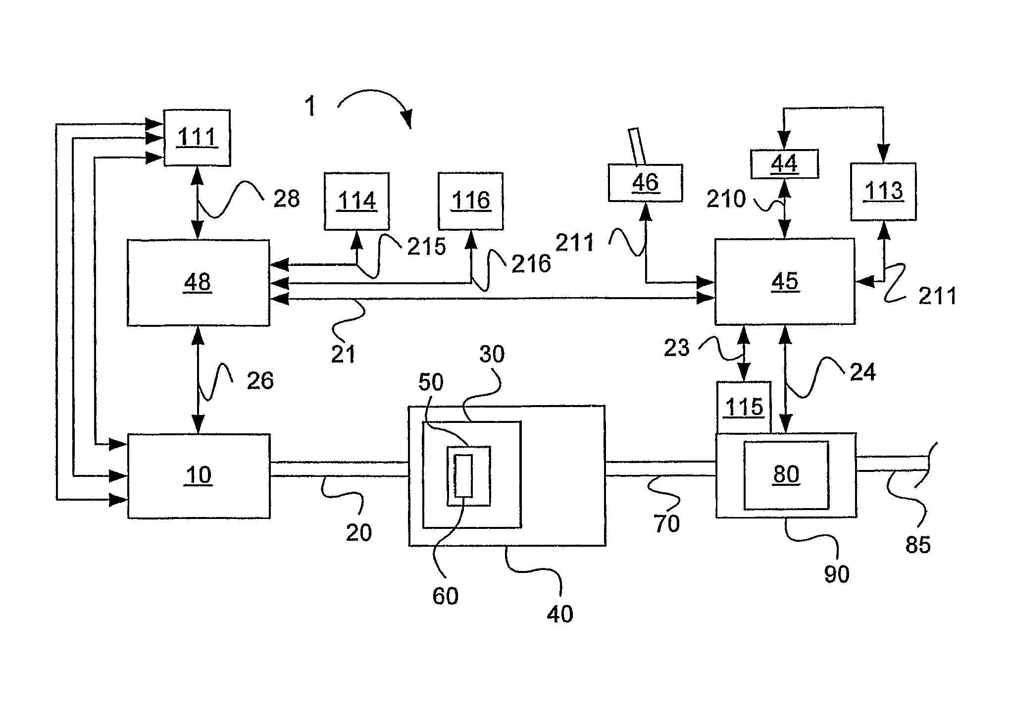
  • Engine driven vehicle with transmission
  • Engine driven vehicle with transmission
  • Engine driven vehicle with transmission

Examples


example

[0057]Calculation example

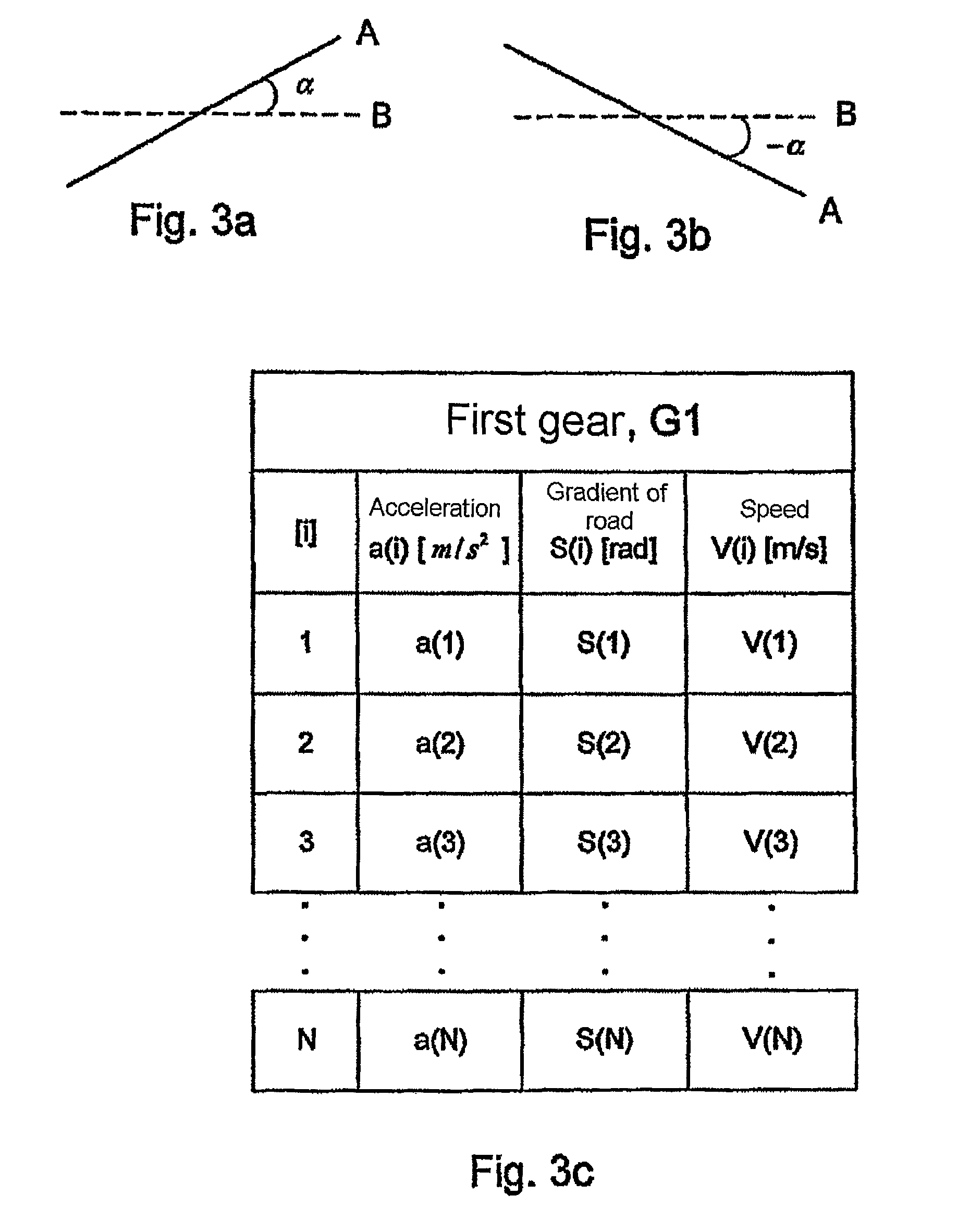
[0058]Assume that the times [i] and [i+4] are used in the calculation, where i=1. A system of equations is then obtained with two unknowns as follows:

0=ma[1]+mg sin(α[1])+k1m+k2V2  [1]

0=ma[5]+mg sin(a[5])+k1m+k2V2  [5]

[0059]Thus, for given values for the vehicle mass m and the acceleration due to gravity g, k1 and k2 can be calculated by solving the system of equations. The calculation is carried out in the second control unit.

[0060]It should be apparent that, according to an embodiment of the present invention, one of k1 and k2 is first calculated and is then used in the calculation of the second constant. This means that the first calculated constant can also be used separately for controlling the vehicle's transmission. The two constants k1 and k2 can thus be used separately for controlling the vehicle's transmission.

[0061]The calculated values k1 and k2 can advantageously be used as the basis for a gear change strategy stored in the second control unit, ...

second embodiment

[0064]According to an embodiment of the invention, the first and the second data groups form the basis for the calculation of the constants k1 and k2 according to the above. S(3), V(3), a(3) and S(4), V(4), a(4) form the basis for the calculation of the constants k1 and k2 with reference to the calculation example above. These can be designated as a third and a fourth data group respectively. Data groups with different time stamps can be used to calculate the constants k1 and k2. For example, a data group 20(R(20)) and a data group 55(R(55)) can be used with reference to the calculation example above.

[0065]Values representing the vehicle's acceleration a, the gradient of the surface on which the vehicle is being driven S and the vehicle's speed V can be communicated in the form of an electrical signal to the second control unit. The signals can alternatively be an optical signal. The signal can be analog or digital. The second control unit is arranged to convert the received signal...


PUM


Abstract

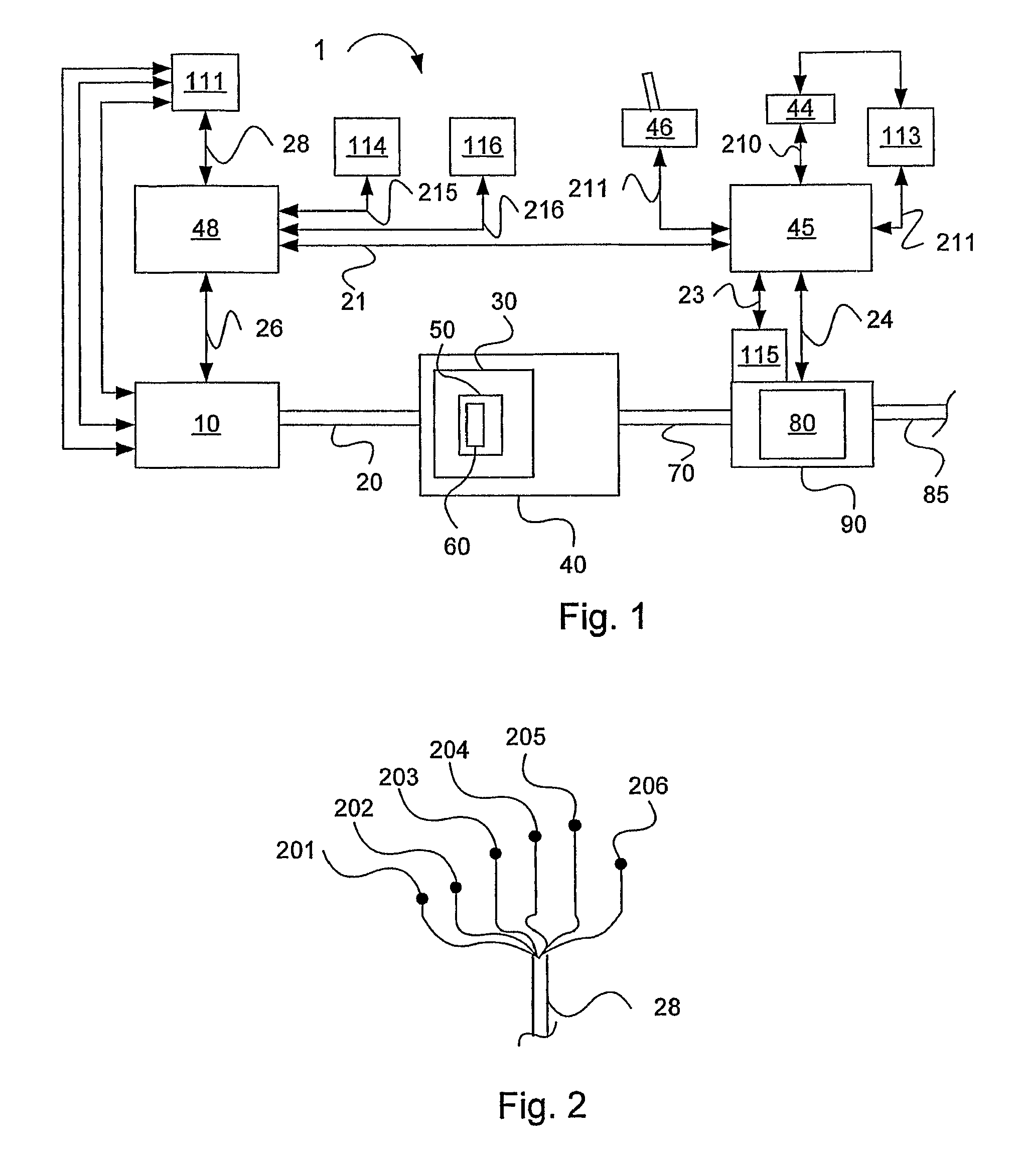
An engine driven vehicle includes at least one engine, and control devices that are arranged to control a transmission that is driven by the engine. The control devices are arranged to receive at least two sets of data, each set including at least one of a first signal that includes information about the gradient of the surface on which the vehicle is being driven sent from a first sensor, and at least one second signal that includes information about the vehicle's speed sent from a second sensor, and at least one third signal that includes information about the vehicle's acceleration. The control devices are also arranged to calculate at least one of two different resistance to travel constants k1 and k2, in response to the first, second and third signals, and to control the transmission in response to at least one of the constants k1 and k2.

Description

BACKGROUND AND SUMMARY[0001]The present invention relates to a motor vehicle comprising an engine and control devices that are arranged to control a transmission that is driven by the engine.[0002]The invention also relates to a method for controlling the vehicle's transmission comprising the determination of the vehicle's resistance to travel.[0003]The invention also relates to a computer program for carrying out the said method.[0004]In vehicles with automatic planetary gearing-based gearboxes with torque-converter or automatic stepping gearboxes, it is important to use as accurate an estimation as possible of the vehicle's resistance to travel—in order to be able to provide optimal gear changing regimes according to certain given criteria, such as, for example, low fuel consumption or high average speed.[0005]A disadvantage of the known technology is the difficulty of controlling the transmission automatically when the vehicle is being driven in changing environments. For example...

Claims


Application Information

Patent Timeline
Patent Type & Authority Patents(United States)
IPC IPC(8): F16H61/02F16H59/36F16H59/14B60KF16H59/44F16H59/66F16H59/48
CPCF16H61/0213F16H59/66F16H2059/142F16H59/48F16H59/44F16H2059/663
Inventor STEEN, MARCUSERIKSSON, ANDERSBLANCKENFIELL, MAGNUSLINDGREN, ANDERS
Owner VOLVO LASTVAGNAR AB
Learn More