Mechanism for controlling a transmission component

a technology of transmission components and control mechanisms, applied in the direction of gearing details, gearing, transportation and packaging, etc., can solve the problems of increasing the number of components required, increasing the number of ratios available, and limited axial space available for the transmission, so as to reduce the number of components, reduce the drag loss, and simplify the brake

Inactive Publication Date: 2014-02-11
FORD GLOBAL TECH LLC
View PDF4 Cites 3 Cited by
  • Summary
  • Abstract
  • Description
  • Claims
  • Application Information

AI Technical Summary

Benefits of technology

[0010]The latching mechanism simplifies the brake, reduces the number of components as compared to the number required for a hydraulically-actuated friction brake, reduces the drag loss by eliminating the friction discs and plates, and requires a smaller space than the space required for a hydraulically-actuated friction brake.
[0011]The latching mechanism is a more robust component and requires lower cost to assemble and install than does a hydraulically-actuated friction brake.

Problems solved by technology

In a front wheel drive vehicle, the axial space available for the transmission is limited by the width of the engine compartment and the length of the engine.
In addition, the trend to increase the number of ratios available generally increases the number of components required.
The ability to position components concentrically is limited, however, by the need to connect particular components mutually and to the transmission case.

Method used


Image

  • Mechanism for controlling a transmission component
  • Mechanism for controlling a transmission component
  • Mechanism for controlling a transmission component

Examples


Embodiment Construction

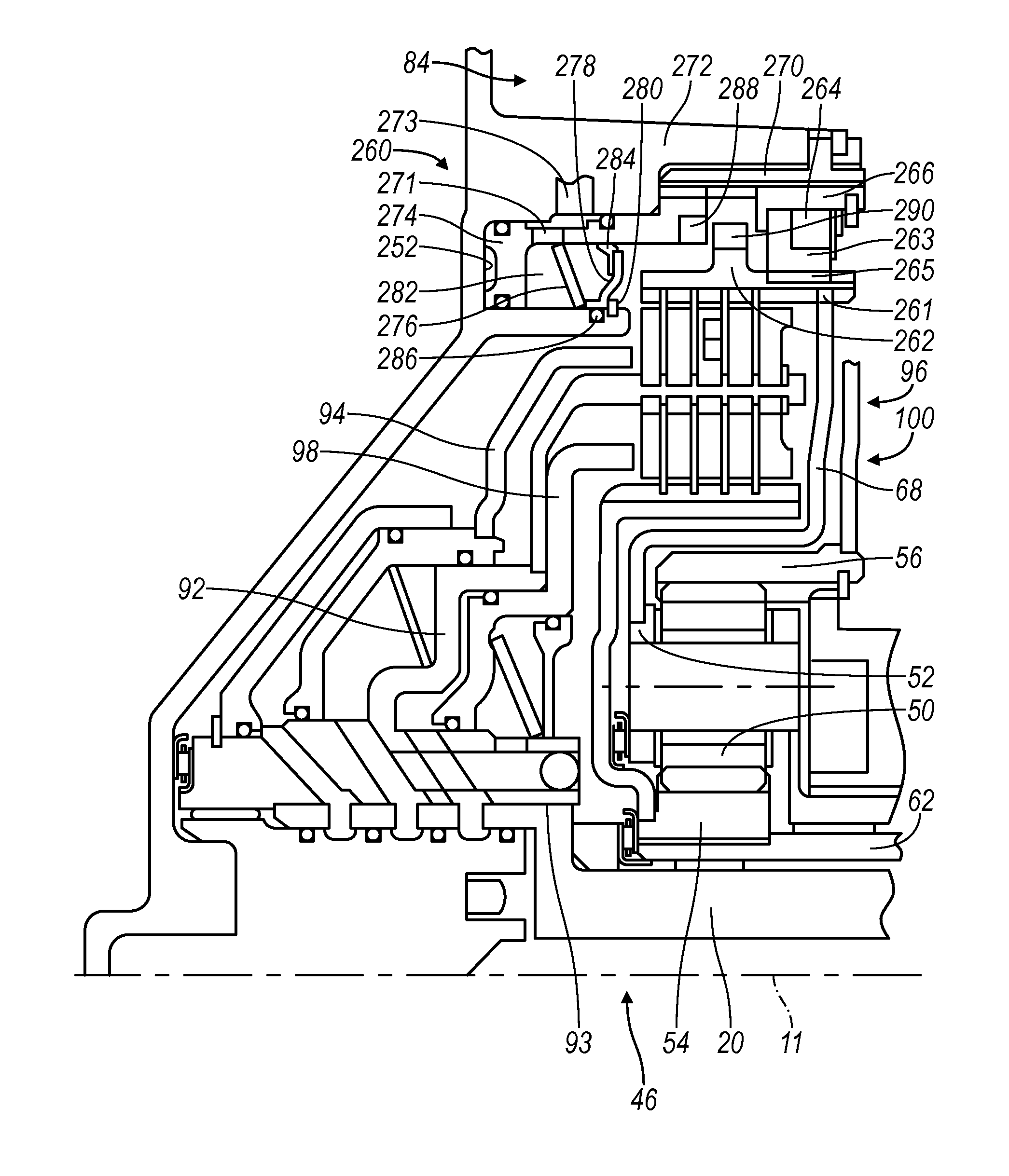
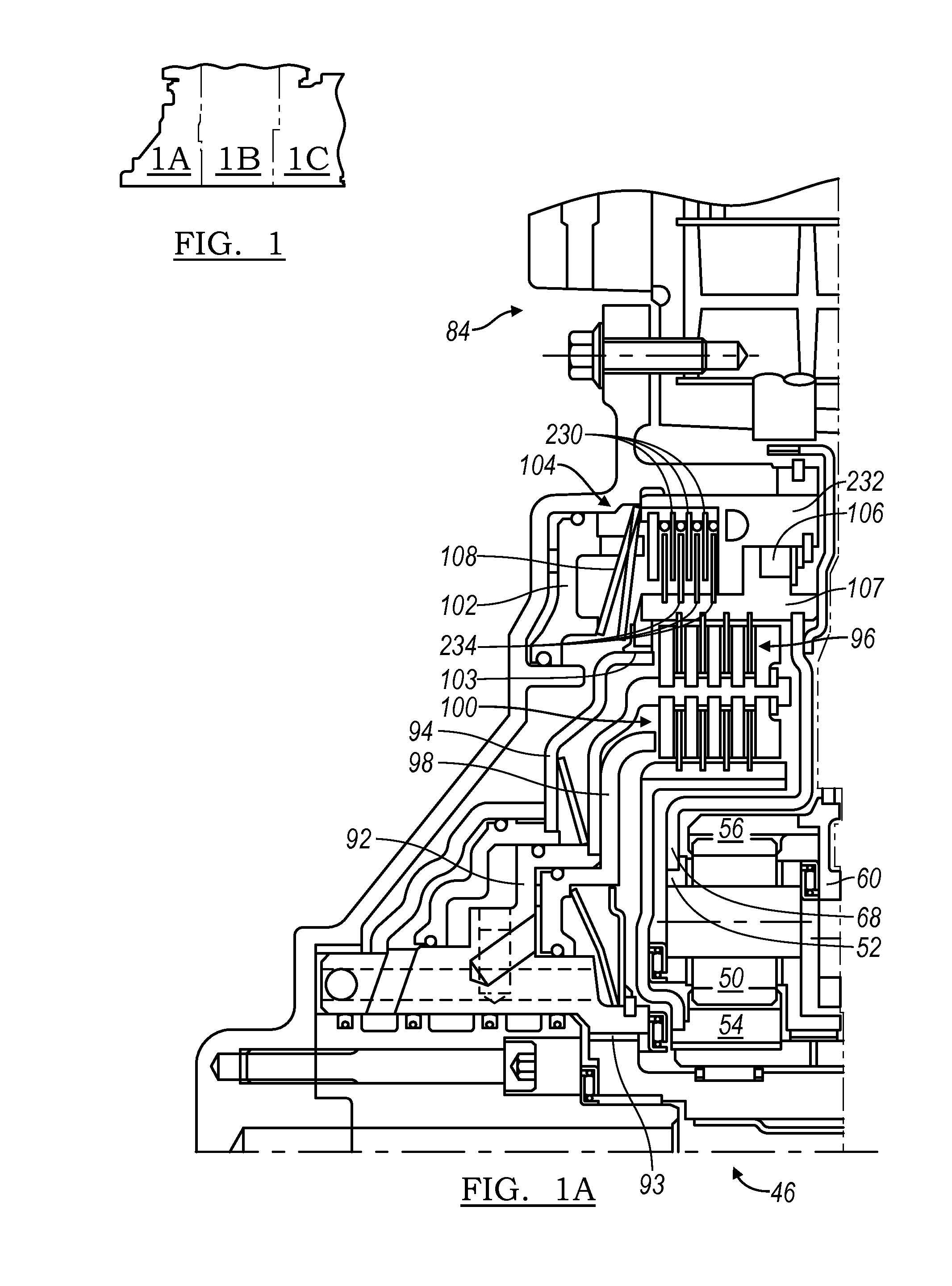
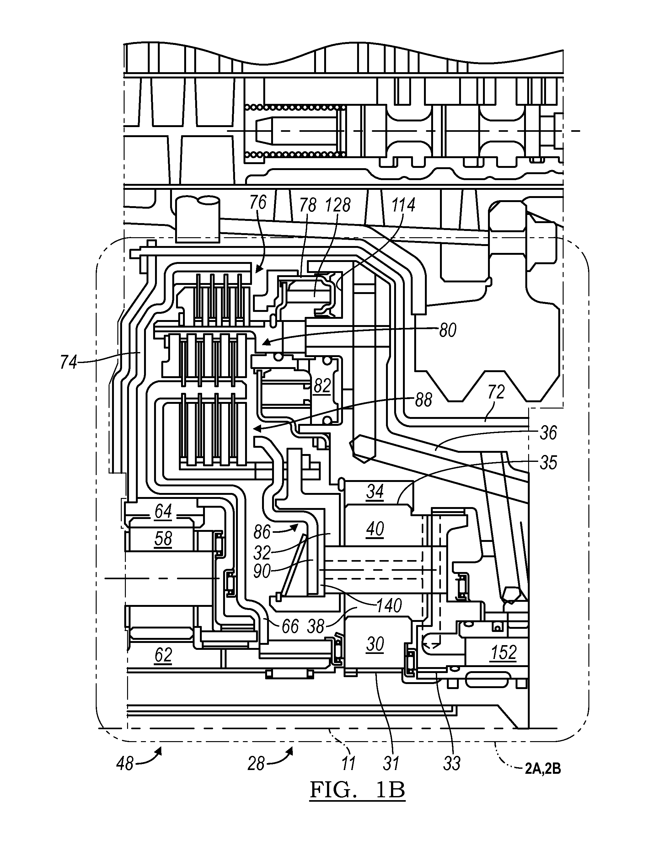
[0019]Referring now to the drawings, FIG. 1 illustrates gearing, clutches, brakes, shafts, fluid passages, and other components of a multiple-speed automatic transaxle arranged substantially concentrically about an axis 11.

[0020]A torque converter includes an impeller driven by an engine, a turbine hydrokinetically coupled to the impeller, and a stator between the impeller and turbine. A transmission input shaft 20 is secured by a spline connection 21 to the turbine. The stator is secured by a spline connection 22 to a front support 24, which is secured against rotation to a transmission case 26.

[0021]A double pinion, speed reduction planetary gearset 28 includes a sun gear 30, secured by a spline connection 31 to input shaft 20; a carrier 32, secured by a spline connection 33 to the front support 24; a ring gear 34, secured by a spline connection 35 to a front cylinder assembly 36; a first set of planet pinions 38 supported on carrier 32 and meshing with sun gear 30; and a second s...


PUM


Abstract

A transmission latching mechanism includes a component of a transmission gearset, a member secured to and able to rotate with the component, and a piston fixed against rotation and moveable alternately to latch the mechanism, thereby holding the member against rotation and to unlatch the mechanism, thereby releasing the member to rotate.

Description

[0001]This application claims priority to and the benefit of U.S. Provisional Application Nos. 61 / 446,147 and 61 / 446,149, filed Feb. 24, 2011, the full disclosures of which are incorporated herein by reference.[0002]This application is a continuation-in-part of pending U. S. application Ser. No. 13 / 052,362, filed Mar. 21, 2011.BACKGROUND OF THE INVENTION[0003]1. Field of the Invention[0004]This invention relates to an automatic transmission for a motor vehicle that includes planetary gearsets and clutches and brakes whose state of engagement and disengagement determines speed ratios produced by the transmission.[0005]2. Description of the Prior Art[0006]In a front wheel drive vehicle, the axial space available for the transmission is limited by the width of the engine compartment and the length of the engine. In addition, the trend to increase the number of ratios available generally increases the number of components required. For these reasons, it is desirable to position componen...

Claims


Application Information

Patent Timeline
Patent Type & Authority Patents(United States)
IPC IPC(8): F16H57/10
CPCF16H63/3023F16H2200/2094F16H2200/2079F16H57/10Y10T74/19637
Inventor JANSON, DAVID A.GOLESKI, GREGORY D.
Owner FORD GLOBAL TECH LLC
Why Eureka
Try Eureka