
An engine braking device positioned by a valve stem

An engine braking and valve valve technology, applied in the directions of engine control, valve drive device, valve device, etc., can solve the problems of unreliable operation of valve lift reset mechanism, difficult installation and debugging, complicated braking system, etc. Compactness, increased reliability and durability, simplified braking effect

Active Publication Date: 2015-08-26
奚勇
View PDF20 Cites 1 Cited by
  • Summary
  • Abstract
  • Description
  • Claims
  • Application Information

AI Technical Summary

Problems solved by technology

[0009] The object of the present invention is to provide a kind of engine braking device positioned by valve stem, and described this engine braking device positioned by valve stem will solve the problem of single rocker arm opening single valve (or single valve) in the prior art. ) in the engine, the brake system is complicated, the valve lift reset mechanism is unreliable, it is not easy to install and debug, the mechanism is bulky, it takes up a lot of space and the technical problems of brake eccentric load

Method used


Image

  • An engine braking device positioned by a valve stem
  • An engine braking device positioned by a valve stem
  • An engine braking device positioned by a valve stem

Examples


Embodiment 1

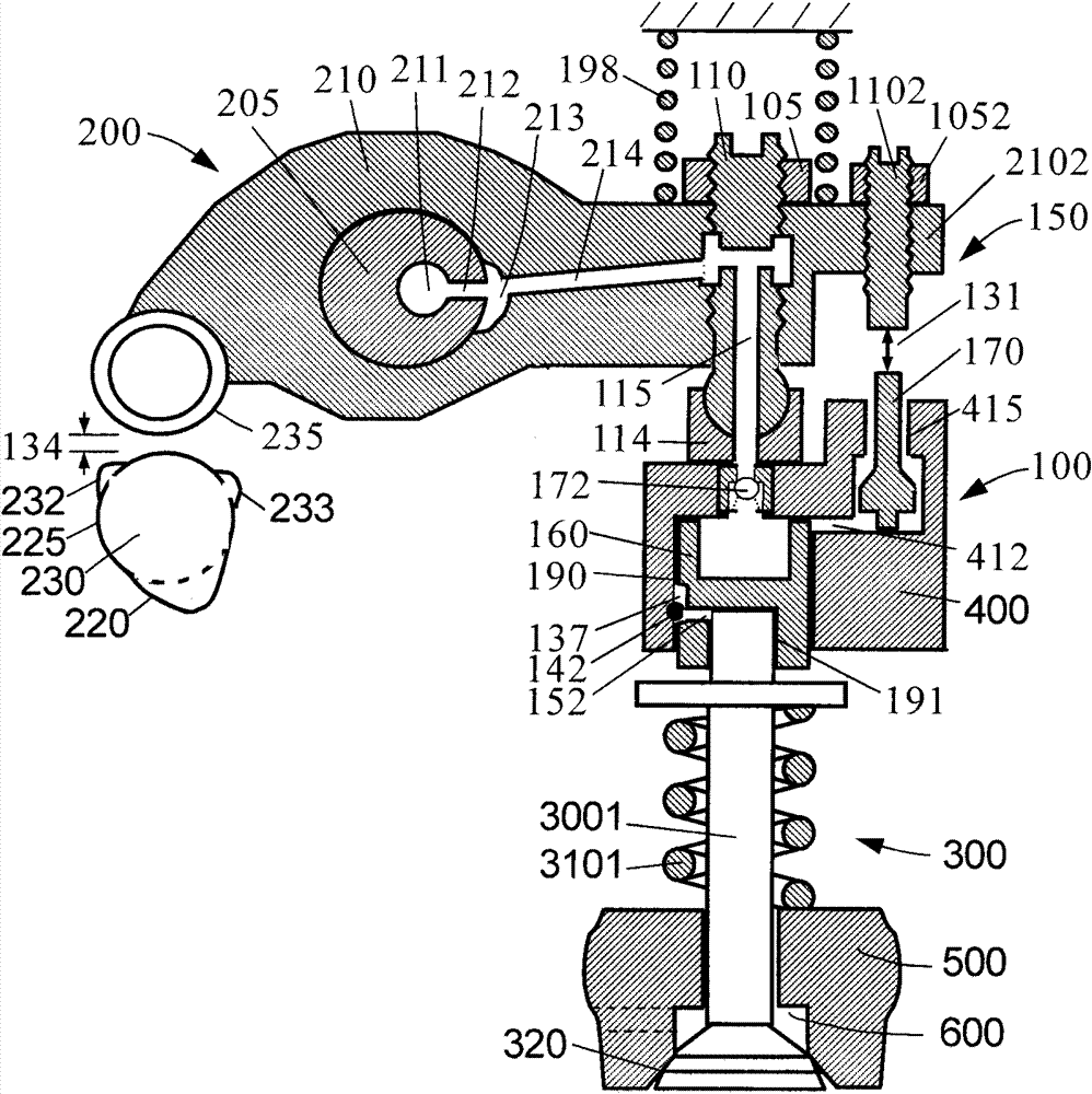
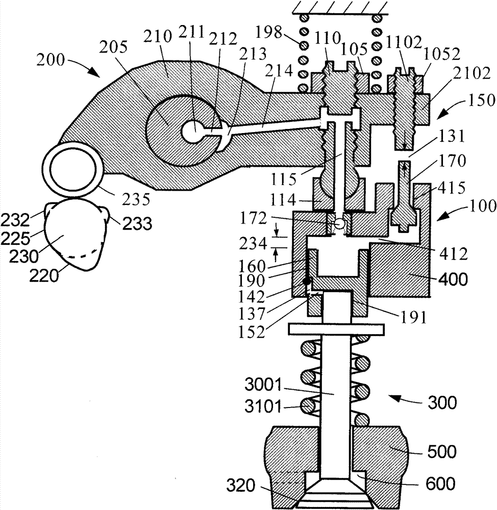
[0041] Such as figure 1 and figure 2 A first embodiment of the valve stem positioned engine braking device of the present invention is shown in its "OFF" and "ON" positions, respectively. figure 1 and figure 2 It includes four main components: an exhaust valve actuator 200 , an exhaust valve mechanism 300 , an engine brake drive mechanism 100 and a valve lift reset mechanism 150 . The exhaust valve actuator 200 and the exhaust valve mechanism 300 form an exhaust valve drive chain.

[0042] Exhaust valve actuator 200 includes a cam 230 , a cam follower 235 and a rocker arm 210 . Rocker arm 210 only drives one exhaust valve 3001 (single rocker arm opens single valve). Usually, one end of the rocker arm 210 (the side close to the valve or the side close to the cam) is provided with a valve gap adjustment system. Because the present embodiment adopts the overhead cam, the valve clearance adjustment system adopts the valve clearance adjustment screw 110 arranged on one side ...

Embodiment 2

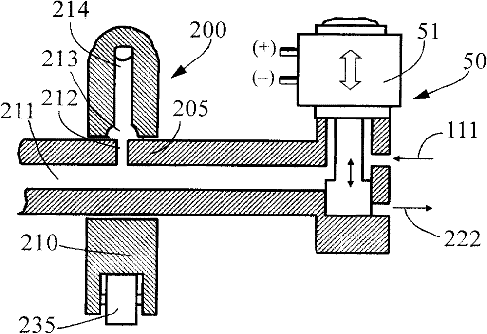
[0063] Such as Figure 6 and Figure 7 A second embodiment of the valve stem positioned engine braking device of the present invention is shown in its "OFF" and "ON" positions, respectively. The main difference between this embodiment and the first embodiment lies in the cam 230 , the brake control mechanism 50 and the valve lift reset mechanism 150 .

[0064] The cam 230 in this embodiment is a conventional engine exhaust cam, and the inner base circle 225 of the cam 230 only has the exhaust boss 220 without adding any braking boss. Therefore, during normal (firing) operation of the engine, there is no brake slack inside the exhaust valve drive train and no preload springs are required to maintain this slack. However, a brake spring 177 is added between the brake piston 160 and the brake piston cylinder liner 400 to help the exhaust valve 3001 open during braking.

[0065] The brake control mechanism 50 of this embodiment includes an exhaust brake device, such as an exhaus...


PUM


Abstract

Disclosed in the present invention is an engine brake device positioned by a valve stem. The device is used in an engine having a single rocker arm for opening a single valve and comprises a brake driving mechanism (100) and a brake control mechanism. The brake driving mechanism (100) comprises a brake piston cylinder sleeve (400), a brake piston (160) and a valve lift resetting mechanism (150). The brake piston cylinder sleeve (400) is located below a rocker arm (210). The brake piston (160) is arranged in a brake piston hole (190) provided on the lower side face of the brake piston cylinder sleeve (400). A brake device positioning hole (191) is arranged on the lower end surface of the brake piston (160), and sleeved on the stem of the valve. The valve lift resetting mechanism (150) can be opened and closed according to the distance between the rocker arm (210) and the brake piston cylinder sleeve (400), so that the valve lift is reset. The brake control mechanism enables the brake driving mechanism (100) to move between a non-operation position and an operation position. The whole brake mechanism is integrated into an existing engine valve drive chain, so the device has a compact structure and can be installed and adjusted conveniently. Consequently, the weight and height of the engine are reduced, the engine brake device is simplified, and the reliability and durability of the engine are improved.

Description

Technical field: [0001] The invention relates to the mechanical field, in particular to the valve drive field of a vehicle engine, in particular to an engine brake device positioned by a valve stem. Background technique: [0002] Engine braking can be classified into compression release type braking and vent type braking. The engine's compression-release brake opens the exhaust valve at the end of the engine piston's compression stroke and closes the exhaust valve at the beginning of the expansion stroke (generally before the exhaust valve normally opens). A precedent for a compression release brake was disclosed in US Patent No. 3,220,392 in 1965 by Cummins. The brake system transmits the mechanical input through the hydraulic circuit to the exhaust valve to open. The hydraulic circuit typically includes a main piston that reciprocates within a main piston bore from a mechanical input to the engine, such as movement of an engine injection cam or movement of an adjacent ex...

Claims


Application Information

Patent Timeline
Patent Type & Authority Patents(China)
IPC IPC(8): F01L13/06F02D13/04
CPCF01L2105/00F01L1/181F01L13/06F02D13/04F01L2820/033F01L1/20F01L13/065F01L1/08F01L2305/00
Inventor 杨洲
Owner 奚勇
Learn More