An integrated engine braking device

An engine braking, integrated technology, applied in the direction of engine control, valve drive, engine components, etc., can solve the problems of unstable reset, difficult installation and debugging, brake eccentric load, etc., to reduce weight and height, The effect of compact structure, increased safety and reliability

Active Publication Date: 2016-02-03
奚勇
View PDF10 Cites 1 Cited by
  • Summary
  • Abstract
  • Description
  • Claims
  • Application Information

AI Technical Summary

Problems solved by technology

[0013] The purpose of the present invention is to provide a new integrated engine braking device, which solves the technical problems in the prior art such as unbalanced braking load or unstable reset, and difficulty in installation and debugging.

Method used


Image

  • An integrated engine braking device
  • An integrated engine braking device
  • An integrated engine braking device

Examples


Embodiment 1

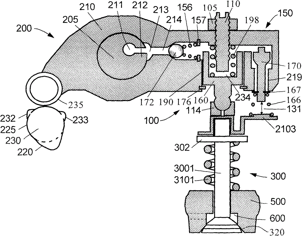
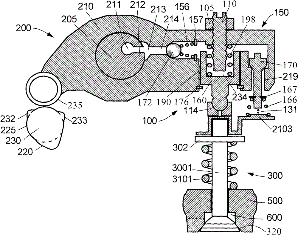
[0056] Such as figure 1 with figure 2 A first embodiment of the integrated engine braking device of the present invention is shown in its "off" and "on" positions, respectively. figure 1 with figure 2 It includes four main components: exhaust valve actuator 200 , exhaust valve mechanism 300 , engine brake drive mechanism 100 and valve lift reset mechanism 150 . The exhaust valve actuator 200 and the exhaust valve mechanism 300 form an exhaust valve drive chain.

[0057] Exhaust valve actuator 200 includes a cam 230 , a cam follower 235 and a rocker arm 210 . Rocker arm 210 only drives one exhaust valve 3001 (single rocker arm opens single valve). Usually, one end of the rocker arm 210 (the side close to the valve or the side close to the cam) is provided with a valve gap adjustment system. Because the present embodiment adopts the overhead cam, the valve clearance adjustment system adopts the valve clearance adjustment screw 110 arranged on one side of the valve 3001 , ...

Embodiment 2

[0076] Such as Image 6 with Figure 7 A second embodiment of the integrated engine braking device of the present invention is shown in its "off" and "on" positions, respectively. The difference between this embodiment and the first embodiment is mainly that the arrangement positions and manners of the pre-tension spring 198 and the reset spring 166 are different. The preload spring 198 is arranged between the rocker arm 210 and the valve 3001 . The lower end of the reset spring 166 is placed on the rocker arm 210 through the spring seat 167 , and the upper end acts directly on the reset piston 170 . In addition, an elephant foot spring 146 is added between the brake piston 160 and the elephant foot pad 114 . Like the foot spring 146, the brake piston 160 is in a retracted non-operating position ( Image 6 ), the brake gap 234 inside the exhaust valve drive chain has moved between the brake piston 160 and the elephant foot pad 114. When the braking device was opened (brak...

Embodiment 3

[0079] Such as Figure 8 with Figure 9 A third embodiment of the integrated engine braking device of the present invention is shown in its "off" and "on" positions, respectively. The difference between this embodiment and the second embodiment is mainly that the reset mechanism 150 is different. Reset piston 170 is contained within a control valve. In addition to the one-way oil supply valve 172, the control valve itself is a sliding plunger valve. In addition, the reset bracket 2103 of the reset mechanism 150 is fixed on the rocker shaft 205 .

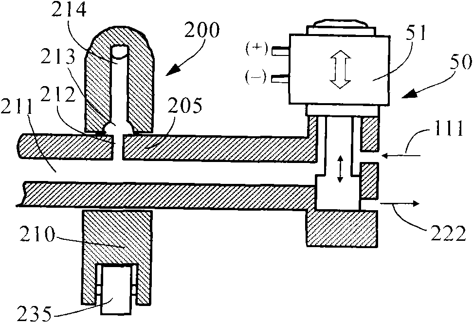
[0080] When engine braking is required, Figure 4 The brake control mechanism 50 is opened, and the solenoid valve 51 supplies the brake drive mechanism 100 ( Figure 8 with 9 ) supply oil. The oil pressure overcomes the active force of the spring 156 and moves the control valve downward to the oil supply position (the reset piston 170 is always at the oil supply position under the action of the reset spring), and the oil flow...


PUM


Abstract

An integrated engine braking device comprises a brake driving mechanism (100) and a brake control mechanism (50). The brake driving mechanism (100) comprises a braking piston (160) integrated in an engine rocker arm (210) and a valve lift reset mechanism (150). The braking piston (160) is located in a braking piston hole (190) in a lower side surface at an end of the rocker arm (210). The upper surface of the braking piston (160) is adjacent to a valve play adjusting screw (110), and the lower surface of the braking piston (160) is located above an exhaust valve (3001) of the engine. The valve lift reset mechanism (150) opens and closes according to the distance between the rocker arm (210) and the exhaust valve (3001), and resets the air valve lift. The brake control mechanism (50) enables the brake driving mechanism (100) to move between a non-operating position and an operating position. The engine braking device is of a compact structure and convenient for mounting and adjustment, reduces the weight and the height of the engine, and improves the reliability and the durability of the engine running.

Description

Technical field: [0001] The invention relates to the mechanical field, in particular to the valve drive field of a vehicle engine, in particular to an integrated engine braking device. Background technique: [0002] In the prior art, engine braking technology is widely known. Engine braking is achieved by temporarily switching the engine to a compressor. The fuel is cut off during the conversion process, and the exhaust valve is opened at the end of the engine piston compression stroke to allow the compressed gas (air during braking) to be released. The energy absorbed by the engine during the compression stroke cannot be used in subsequent expansion. The stroke returns to the engine pistons, but is dissipated through the engine's exhaust and cooling system. The end result is effective engine braking that slows the vehicle. [0003] One precedent for an engine braking device is the hydraulic engine brake disclosed in US Patent No. 3,220,392 by Cummins in 1965. The engine...

Claims


Application Information

Patent Timeline
Patent Type & Authority Patents(China)
IPC IPC(8): F01L13/06F01L1/24F02D13/04
CPCF01L1/08F01L1/181F01L13/06F01L2800/10F02D13/04F02D13/06F01L9/10
Inventor 杨洲
Owner 奚勇
Why Eureka
Try Eureka