Braking method and device of integrated exhaust type engine
An engine braking and integrated technology, applied in the direction of engine control, engine components, machine/engine, etc., can solve problems such as poor reliability and durability, increased engine height and weight, inconvenient installation and debugging, etc., to achieve Increased reliability and durability, reduced weight and height, and compact structure
- Summary
- Abstract
- Description
- Claims
- Application Information
AI Technical Summary
Problems solved by technology
Method used
Image
Examples
Embodiment 1
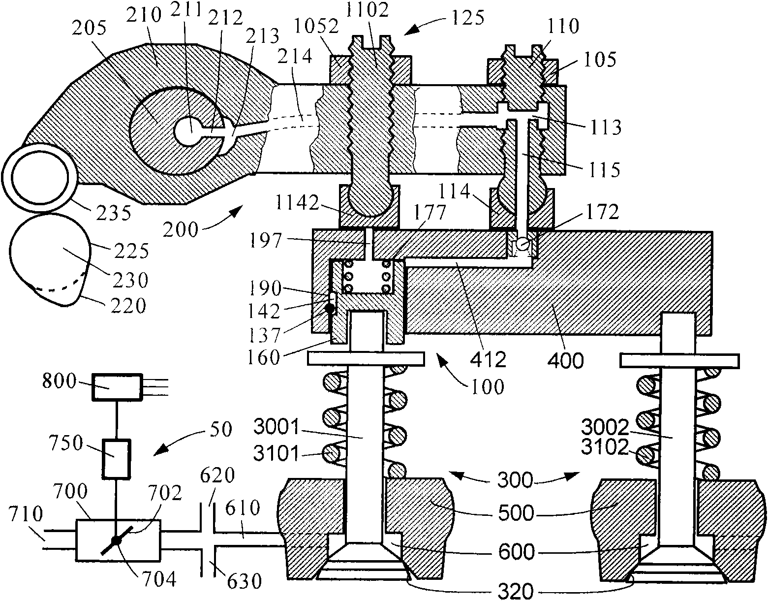
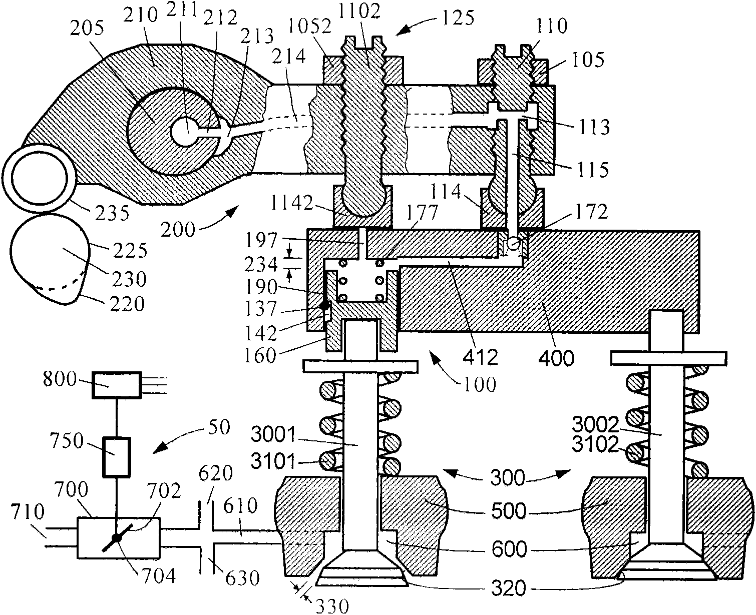
[0045] Such as figure 1 and figure 2 A first embodiment of the integrated vented engine braking device of the present invention is shown in its "off" and "on" positions, respectively. The figure includes four main components: an exhaust valve actuator 200 , an exhaust valve 300 (including an inner exhaust valve 3001 and an outer exhaust valve 3002 ), an engine brake driving mechanism 100 and an engine brake control mechanism 50 .
[0046] Exhaust valve actuator 200 includes cam 230 , cam follower 235 , rocker arm 210 and valve bridge 400 . Usually, one end of the rocker arm 210 (the side close to the valve bridge or the side close to the cam) has a valve clearance adjustment system. In this embodiment, a valve gap adjusting screw 110 is provided on one side of the valve bridge 400 , and the valve gap adjusting screw 110 is located on the rocker arm 210 and fixed by the locking nut 105 . The valve gap adjusting screw 110 is connected with the elephant foot pad 114 , and the...
Embodiment 2
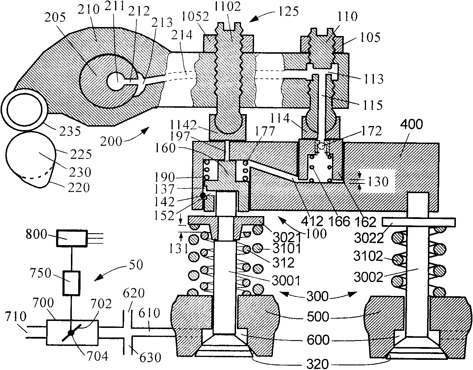
[0056] Such as image 3 and Figure 4 A second embodiment of the integrated vented engine braking device of the present invention is shown in its "off" and "on" positions, respectively. The main differences between this embodiment and the first embodiment are:
[0057] 1. An automatic valve gap adjustment mechanism is added. The automatic valve gap adjustment mechanism includes an adjustment piston 162 and an adjustment spring 166 . The regulating piston 162 is located in an upwardly opening central bore in the valve bridge 400 . The adjusting spring 166 is located between the adjusting piston 162 and the valve bridge 400 , biasing the adjusting piston 162 upwardly against the foot pad 114 . The one-way oil supply valve of the oil supply mechanism is located in the regulating piston 162 . A valve gap 130 is provided between the regulating piston 162 and the valve bridge 400 . The valve gap 130 is smaller than the stroke 234 of the brake piston 160 (the distance between t...
Embodiment 3
[0064] Such as Figure 5 and Figure 6 A third embodiment of the integrated vented engine braking device of the present invention is shown in its "OFF" and "ON" positions, respectively. The oil supply mechanism in this embodiment is integrated with the supporting mechanism 125 . There is an oil supply piston 162 inside the adjustment screw 1102 of the support mechanism 125 . There is a hydraulic channel 115 in the oil supply piston 162 , which communicates with the hydraulic channel 214 in the rocker arm 210 through the horizontal oil hole 113 in the adjusting screw 1102 . A one-way oil supply valve 172 is arranged in the hydraulic flow channel 115 . In addition, the unloading channel 197 in the valve bridge 400 is also an oil supply channel at the same time. The sealing ring 173 disposed in the end face of the oil supply piston 162 can prevent leakage caused by uneven or misaligned contact surfaces.
[0065] When engine braking is required, the brake control mechanism 50...
PUM
 Abstract
Description
Claims
Application Information
 - R&D
- Intellectual Property
- Life Sciences
- Materials
- Tech Scout
- Unparalleled Data Quality
- Higher Quality Content
- 60% Fewer Hallucinations
Browse by: Latest US Patents, China's latest patents, Technical Efficacy Thesaurus, Application Domain, Technology Topic, Popular Technical Reports.
© 2025 PatSnap. All rights reserved.Legal|Privacy policy|Modern Slavery Act Transparency Statement|Sitemap|About US| Contact US: help@patsnap.com


