
Autostereoscopic display device

a display device and autostereoscopic technology, applied in the field of autostereoscopic display devices, can solve the problems of sacrificing resolution, shallow three-dimensional images with little depth perception, and difficult to provide a display having a good image resolution, wide viewing angle and good depth perception, so as to achieve the effect of “consuming” both vertical and horizontal resolution, increasing the number of views displayed, and sacrificing resolution

Active Publication Date: 2014-02-11
KONINK PHILIPS ELECTRONICS NV +1
View PDF19 Cites 2 Cited by
  • Summary
  • Abstract
  • Description
  • Claims
  • Application Information

AI Technical Summary

Benefits of technology

The patent text describes a display device that can increase the number of views and the useful viewing angle by sequentially driving a spatial light modulator with display data for different pluralities of views. The light from the spatial light modulator is incident on each of the view forming elements with sequentially changing angular distributions, and in this case, the different pluralities of views are projected towards the user in different horizontal directions. This technique can sacrifice resolution to some extent, but it allows for a display device with a wide viewing angle and / or a good perception of depth.

Problems solved by technology

However, it will be appreciated that, in order to provide stereoscopic views, there is a necessary sacrifice in the horizontal resolution of the device causing a substantial difference between vertical and horizontal resolution in autostereoscopic mode.
However, such a display provides a shallow three dimensional image with little perception of depth.
Consequently, using known techniques, it is difficult to provide a display having a good image resolution, a wide viewing angle and a good perception of depth.

Method used


Image

  • Autostereoscopic display device
  • Autostereoscopic display device
  • Autostereoscopic display device

Examples


Embodiment Construction

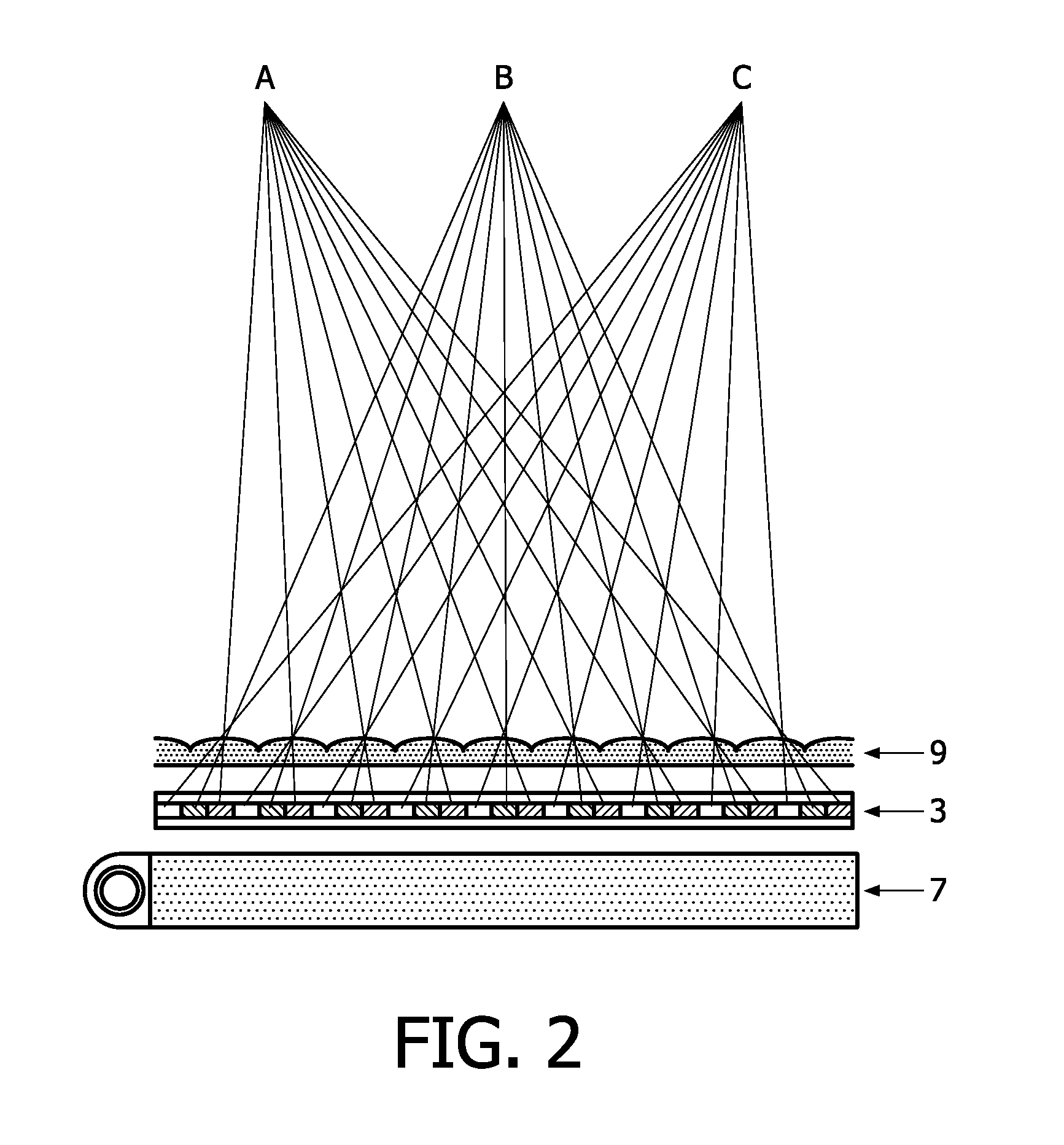
[0050]The invention provides an autostereoscopic display device of the type that has a backlight, a spatial light modulator and a view forming layer. The spatial light modulator is sequentially driven with display information for different pluralities of views or different elements of the same plurality of views. Simultaneously, the backlight is driven to provide view forming elements of the view forming layer with modulated light having sequentially changing angles of incidence. These changing angles of incidence cause the different pluralities of views or the different elements of the same plurality of views to be projected towards to user to provide an increased number of views or views having an increased resolution.

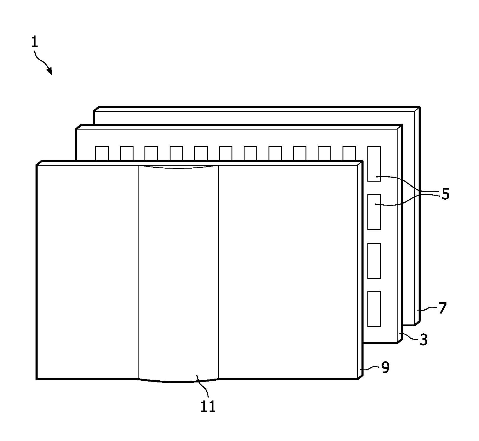
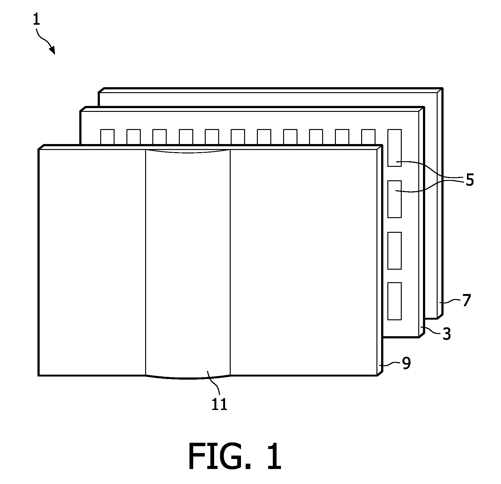
[0051]FIG. 1 is a schematic perspective view of a known multi-view autostereoscopic display device 1. The known device 1 comprises a liquid crystal display panel 3 of the active matrix type that acts as a spatial light modulator to produce the display.

[0052]The displ...


PUM


Abstract

A multi-view autostereoscopic display device comprises: a backlight having a plurality of backlight areas arranged in a width direction of the display device; a spatial light modulator arranged over and in registration with the backlight, the spatial light modulator having an array of display forming elements arranged in rows and columns for modulating light received from the backlight; and a view forming layer arranged over and in registration with the spatial light modulator, the view forming layer having a plurality of view forming elements arranged in the width direction of the display device, each view forming element being configured to focus modulated light from adjacent groups of the display forming elements into a plurality of views for projection towards a user in different directions. The backlight is switchable to activate different ones of the backlight areas in different portions of a driving cycle of the display device so that, in the different portions of the driving cycle, modulated light from the active backlight areas is incident on each view forming element with respective different angles of incidence. In this way, the overall viewing angle or the effective three dimensional display resolution may be increased.

Description

FIELD OF THE INVENTION[0001]This invention relates to an autostereoscopic display device comprising an image forming means, such as a display panel having an array of display pixels, and a view forming means through which the display pixels are viewed. The invention also relates to a method of driving an autostereoscopic display device and a computer programmed product.BACKGROUND OF THE INVENTION[0002]GB 2196166 A discloses an autostereoscopic display device that comprises a two dimensional liquid crystal display panel having a row and column array of display pixels acting as an image forming element to produce the display. An array of lenticular elements extending parallel to one another overlies the display pixel array and acts as a view forming element. The display pixels are observed through these lenticular elements.[0003]The lenticular elements are provided as a sheet of elements, each of which comprises an elongate semi-cylindrical lens element. The lenticular elements extend...

Claims


Application Information

Patent Timeline
Patent Type & Authority Patents(United States)
IPC IPC(8): G09G5/10G02B27/22G09G3/36G09G3/00H04N13/04
CPCH04N13/0445H04N13/0404H04N13/0418H04N13/305H04N13/32H04N13/349
Inventor REDERT, PETER-ANDREKRIJN, MARCELLINUS PETRUS CAROLUS MICHAEL
Owner KONINK PHILIPS ELECTRONICS NV
Learn More