
Sensor arrangement for determining an inside temperature in a motor vehicle

a technology for motor vehicles and sensors, applied in the direction of heat measurement, instruments, calibrators, etc., can solve the problem of insufficient control of the inside temperature, and achieve the effect of simple configuration

Active Publication Date: 2014-02-18
PREH GMBH
View PDF17 Cites 5 Cited by
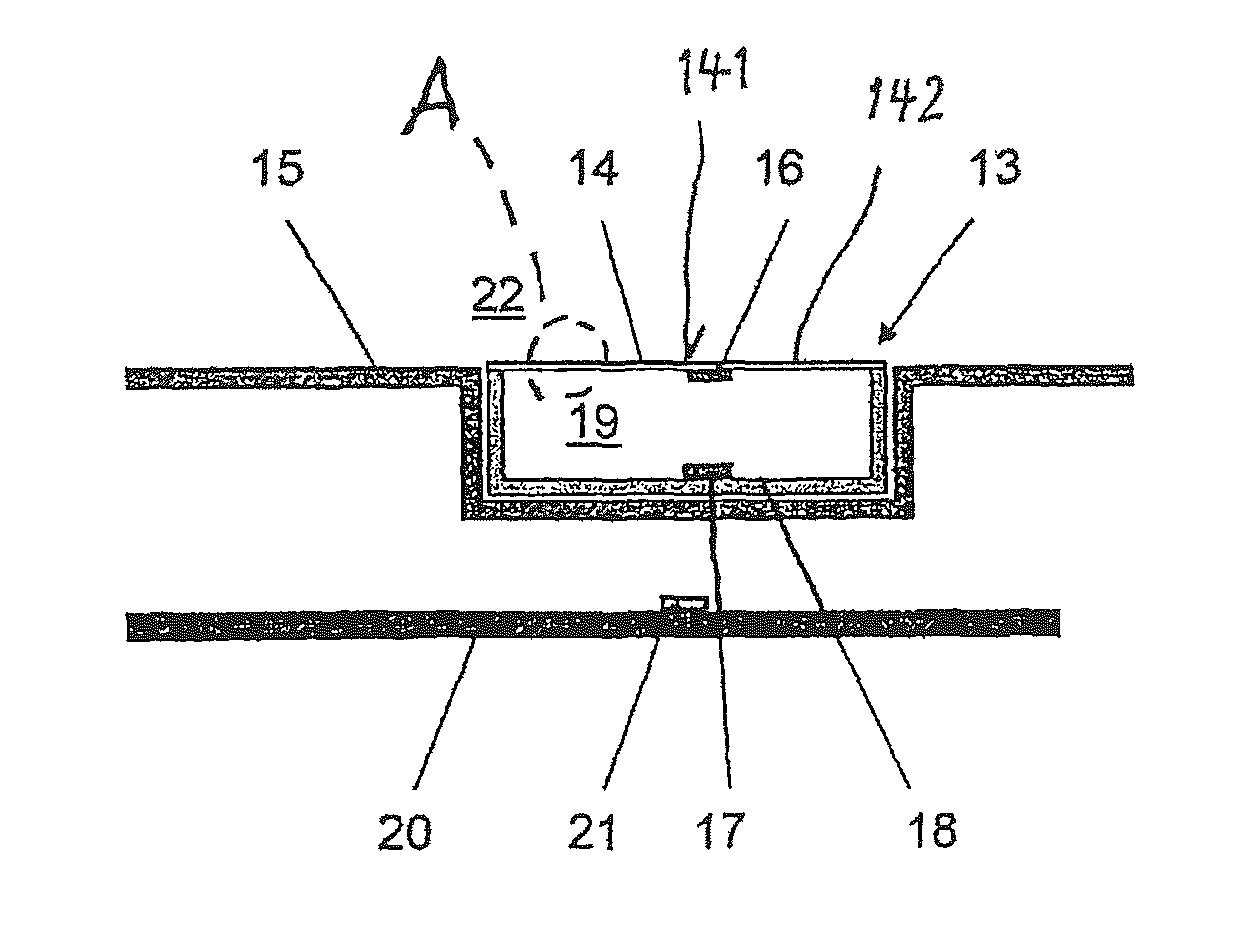
  • Summary
  • Abstract
  • Description
  • Claims
  • Application Information

AI Technical Summary

Benefits of technology

[0005]The disclosure provides a sensor arrangement which has a structurally simple configuration, which can be realized in an inexpensive manner, and which can be installed in the vehicle independent from the position of the climate control device.
[0006]This is achieved by the front wall of the sensor arrangement being a part of a panel in the motor vehicle, wherein the front wall has such a wall thickness that heat transfer through the front wall is ensured. The structure according to the invention of a sensor arrangement has now created the possibility of attaching the sensor arrangement at any position within the climate control part, but also at any other position, such as, for example, in the dashboard, the center console or the coverings. Disposing the sensor behind a panel creates an opportunity of adapting the panel to the interior of the motor vehicle and thus to install the sensor arrangement at any position and, advantageously, also beyond the heat radiation of peripheral devices into the motor vehicle. In contrast to the prior art, the arrangement is not restricted to geometric and / or design-related and / or aesthetic positions in the climate control part, so that a greater latitude is provided for designing the climate control part. On the one hand, this has an effect on the design-related arrangement within the climate control part, as well as on the possibility of disposing the sensor arrangement at a position in the motor vehicle that is optimal for the measurement.
[0007]Thus, this provides the advantage that the position in the motor vehicle which is suitable for an optimum measurement of the inside temperature can be used for measuring the inside temperature. It is conceivable, for example, that, for operating reasons, the climate control device is disposed such that it is exposed to a direct insolation. This results in an advantage that is essential in the invention, namely that the sensor arrangement can be shifted into an area that is not subjected to direct insolation.
[0008]Another advantage results from the fact that a reduced number of components can be employed. Where the sensor arrangement in accordance with the prior art are dependent upon the front walls composed of a good thermal conductivity are disposed as independently as possible from the interior, such as the panel or the dashboard, the sensor arrangement according to the invention can be produced with considerably less effort, because a separate freely suspended front wall is omitted, which in turn has a beneficial effect on the production costs.
[0009]Another advantage results in that dividing the components of the climate control device, of which the sensor arrangement is a part, is made easier. Now, the sensor arrangement is not bound anymore to any design parameters, but can be installed in a location in the climate control part which, depending on other components of the climate control part, offers options for an arrangement. These advantages relating to the constructional space are in turn advantageous in construction, so that a positive effect with regard to the production costs also becomes evident in this respect.

Problems solved by technology

For example, in particular direct insolation can distort the measured value, which in turn leads to an insufficient control of the inside temperature.

Method used


Image

  • Sensor arrangement for determining an inside temperature in a motor vehicle
  • Sensor arrangement for determining an inside temperature in a motor vehicle

Examples


Embodiment Construction

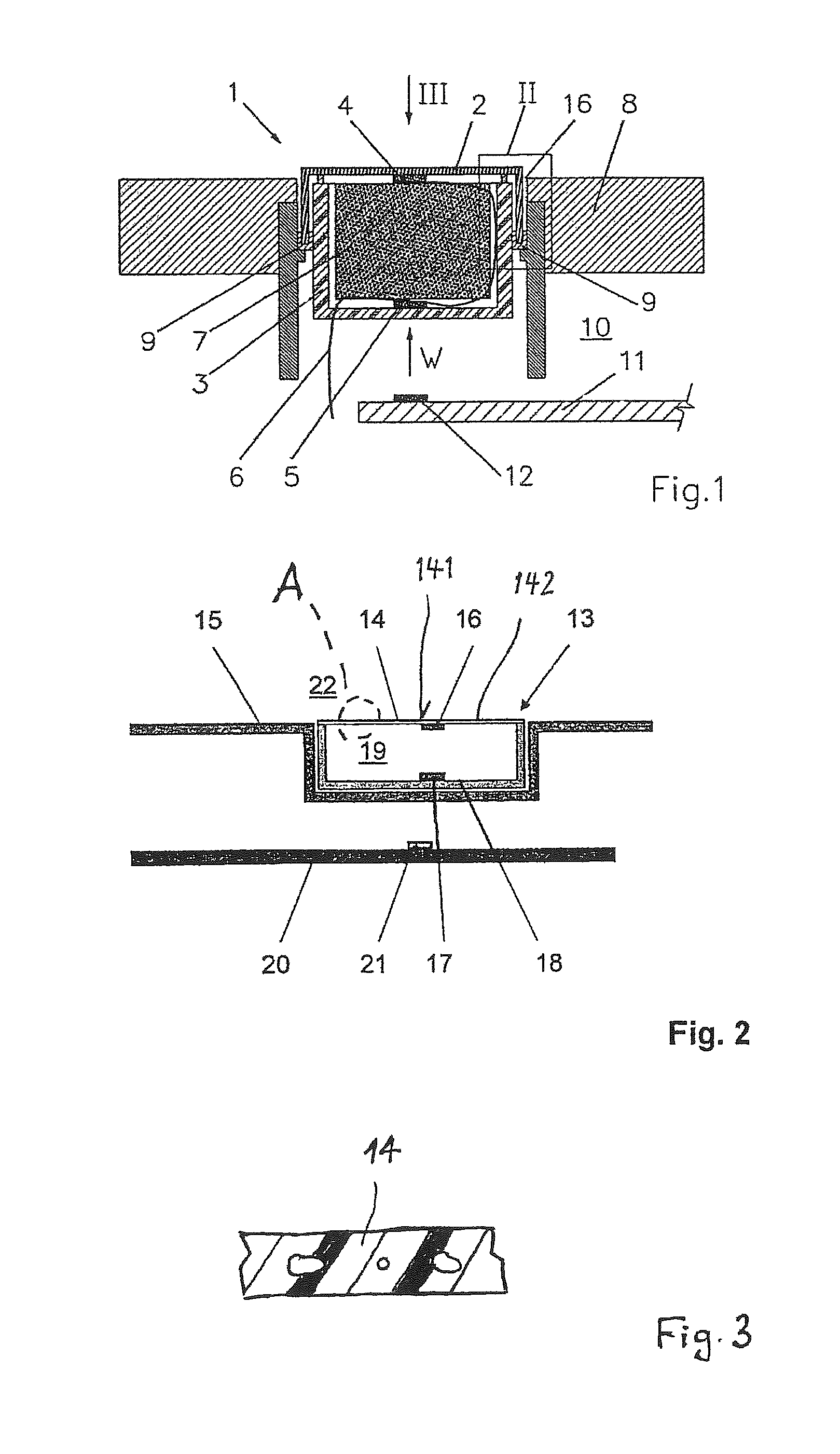
[0014]FIG. 1 shows a sensor arrangement 1 according to DE 10 2007 009 672 as a surface sensor 1, comprising a front wall 2 which is part of the housing of the surface sensor 1, a rear wall 3 primarily fabricated from plastic as a rear housing part, a first temperature sensor 4 and a second temperature sensor 5, a flexible line 6, wherein the flexible line 6 is connected to the two temperature sensors 4, 5, and a heat-insulating material 7 located within the housing 2, 3, which on the one hand fills the housing 2, 3 and on the other hand provides an insulating effect between the temperature sensors 4, 5. The surface sensor 1 is integrated flush or almost flush with a panel 8 of the control device of an air-conditioning system. The sensor arrangement 1 is retained in the panel 8 by means of guide ribs 9. A circuit board 11 is shown behind the surface sensor 1 on the inside of the climate control device. Another temperature sensor 12 is attached to the circuit board 11. Direct referenc...


PUM

PropertyMeasurementUnit
thicknessaaaaaaaaaa
thicknessaaaaaaaaaa
thicknessaaaaaaaaaa

Abstract

A sensor arrangement for determining an inside temperature in a motor vehicle having a climate control device and at least a panel is at least a part of a control part of the climate control device, where the sensor arrangement includes a housing with at least a front wall and a rear wall, the housing is filled with a heat-insulating material, a first temperature sensor attached to a rear of the front wall and a second temperature sensor attached to an inner side of the rear wall, said inner side facing a rear of the front wall, and where the front wall is a part of the panel of the motor vehicle.

Description

TECHNICAL FIELD[0001]The invention relates to a sensor arrangement for determining an inside temperature in a motor vehicle which is at least a part of a climate control part, including a housing with at least a front wall and a rear wall, wherein the housing is filled with a heat-insulating material, a first temperature sensor attached to a rear of the front wall and a second temperature sensor attached to an inner side of the rear wall, said inner side facing the rear of the front wall.BACKGROUND[0002]Controlled air-conditioning systems are being used in motor vehicles for maintaining a pre-settable temperature. Various sensors are used for detecting the actual value of the inside temperature. The sensors are frequently integrated into the climate control devices of the motor vehicles in order to form a self-contained unit. In order to obtain the actual value, different influences on a sensor arrangement for detecting the actual temperature have to be taken into account. For examp...

Claims


Application Information

Patent Timeline
Patent Type & Authority Patents(United States)
IPC IPC(8): G01K1/08
CPCG01K1/20G01K1/14
Inventor REGENSBURGER, JOHANNBAUER, GEORGKRAMLICH, ANDREASREISER, MICHAELGUCK, CLAUDIA
Owner PREH GMBH
Learn More