Fastening device for mounting on a mounting rail

a technology of fastening device and mounting rail, which is applied in the direction of threaded fasteners, fastening means, screws, etc., to achieve the effect of simplifying the constructional design of the fastening device and simplifying the correct insertion

Active Publication Date: 2014-02-18
HILTI AG
View PDF11 Cites 6 Cited by
  • Summary
  • Abstract
  • Description
  • Claims
  • Application Information

AI Technical Summary

Benefits of technology

[0007]An object of the present invention is to provide a fastening device that will be more flexible with respect to the mounting rail geometry and that will ensure a precise orientation of the rear-engagement member for introducing force into the mounting rail in the tensioned state.
[0012]The at least one stop element preferably projects from the contact side of the contact plate facing the rear-engagement member, thereby facilitating an especially simple constructional design of the fastening device. The entire width of the at least one stop element advantageously corresponds maximally to the clearance width of the mounting opening, so that, when the fastening device is placed between the rims of the mounting opening, the at least one stop element is able to penetrate into the interior space of the mounting rail to allow the contact plate to rest flat on the outside of the mounting rail.
[0013]The holding device for the rear-engagement member is preferably provided on the stop element, thereby allowing the stop element to be used at the same time to space apart the rear-engagement member and the contact plate in a defined manner, which simplifies a correct insertion of the rear-engagement member into the mounting opening and a subsequent rotation of the rear-engagement member underneath the free ends of the rims of the mounting opening. If the at least one stop element projects from the contact plate, then the holding device is advantageously provided on the free end of the at least one stop element. The holding device includes a holding pin, for example, which engages into a retaining recess for holding the rear-engagement member in the preloaded position.
[0018]A second spring element is preferably provided between a section of the tensioning device, at the end thereof facing away from the rear-engagement member, and the contact plate, to spring-load a part of the tensioning device that is connected to the rear-engagement member, in the direction of the end facing away from the rear-engagement member, thereby providing an advantageous preloading of the rear-engagement member in the direction of the contact plate. The second spring element is advantageously designed as a coil spring which, for example, acts on a bolt head or a radially projecting expanded portion at the end of the tensioning device facing away from the rear-engagement member.
[0021]At its end facing away from the rear-engagement member, the tensioning device preferably has a mount for a rod element, thereby enabling the fastening device to be used directly as a connecting element for a clamp connection or for hanging a component on the mounting rail. Advantageously provided in the mount is a thread, for example, an internal thread, into which a rod element, such as a threaded rod, which is provided, at least in some regions, with a thread, for example, an external thread, is able to be screwed in and detachably secured in position. The mount is advantageously a through bore that extends over the entire longitudinal extension of the corresponding part of the tensioning device, thereby providing a large area for adjusting and positioning the rod element relative to the mounting rail.

Problems solved by technology

The drawback of the known approach is that it requires that this fastening device be adapted to a special geometry of the mounting rail, in particular, to the geometry of the mounting opening, since, otherwise, the rear-engagement member can be subject to overtwisting, or, upon release of the holding device, not be in an ideal orientation for engaging behind the rims of the mounting opening to optimally clamp the fastening device to the mounting rail.

Method used


Image

  • Fastening device for mounting on a mounting rail
  • Fastening device for mounting on a mounting rail
  • Fastening device for mounting on a mounting rail

Examples


Embodiment Construction

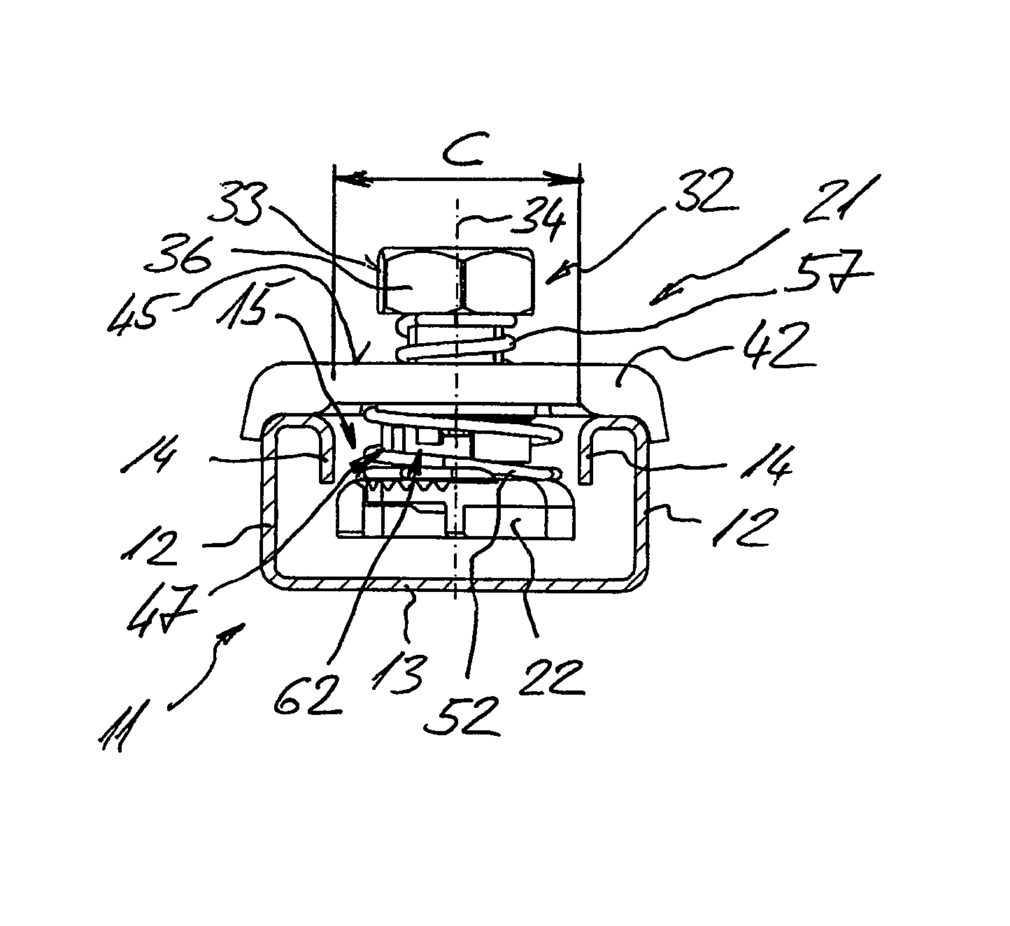
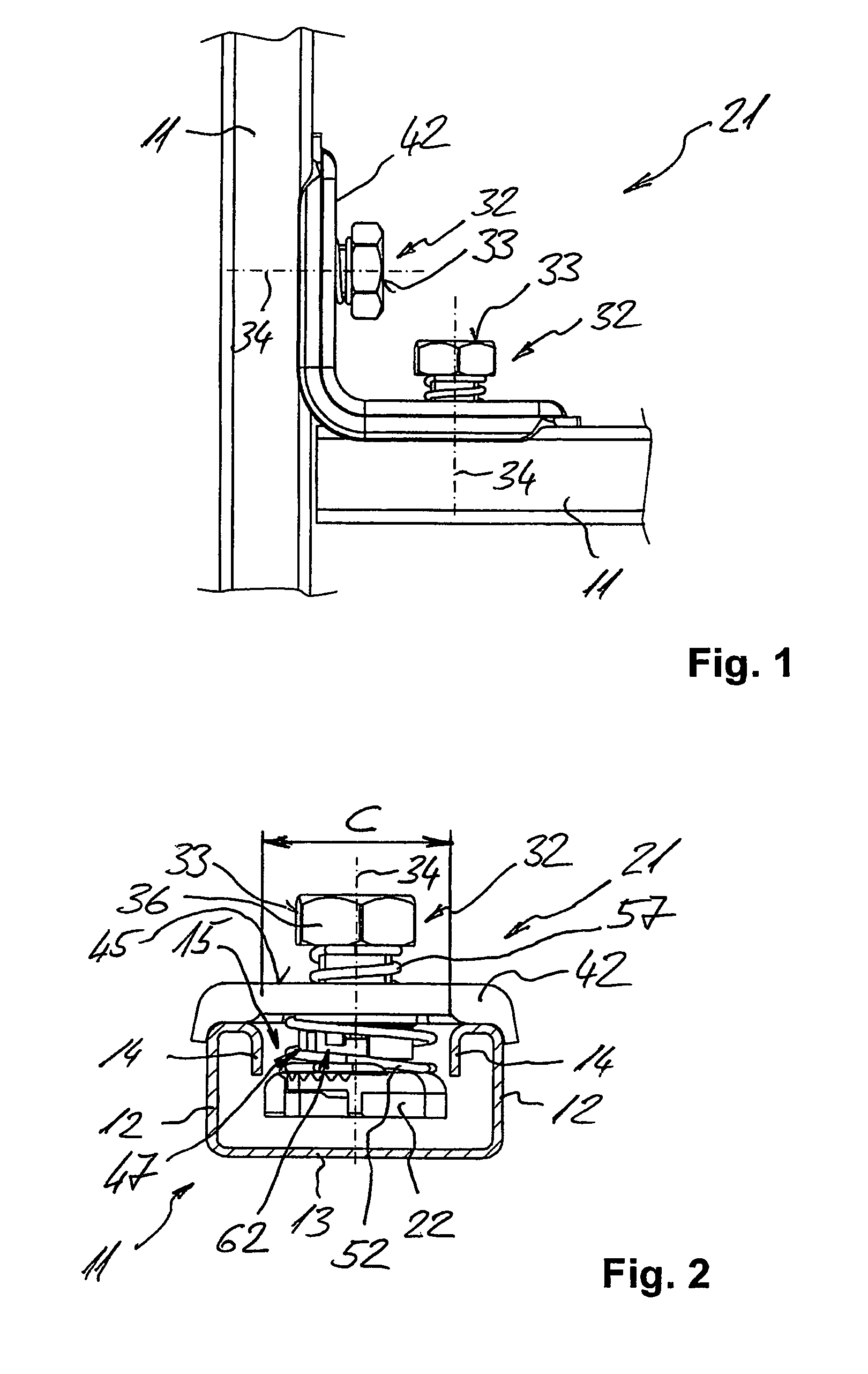
[0036]Fastening device 21 illustrated in FIG. 1 through 5 is used for connecting two C-shaped mounting rails 11.

[0037]Mounting rails 11 each have two mutually opposing side walls 12, a rear wall 13 joining these side walls 12, as well as a mounting opening 15 facing opposite this rear wall 13, bounded by rims 14, and extending along the longitudinal extension of mounting rail 11. Mounting opening 15 has a clearance width C extending transversely to the longitudinal extension of mounting rail 11 that is defined by the inwardly bent free ends of rims 14. Each mounting rail 11 encloses an interior space which is externally accessible through mounting opening 15.

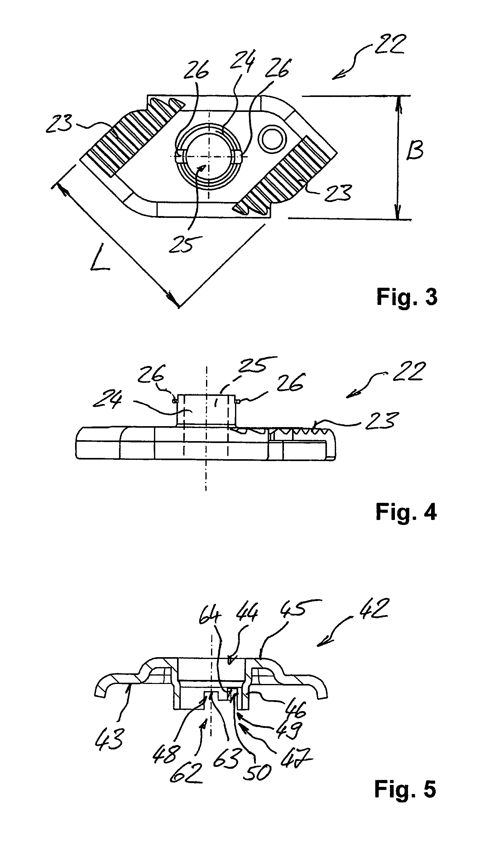
[0038]Fastening device 21 has a rear-engagement member 22 having a width B that is smaller than clearance width C of mounting opening 15 in mounting rail 11, and a length L that is greater than clearance width C of mounting opening 15 in mounting rail 11. Clamping surfaces 23 of rear-engagement member 22 are toothed to facilitat...


PUM


Abstract

A fastening device (21) for mounting on a mounting rail (11) having a rear-engagement member (22) which is configured to be introduced into the mounting opening (15) and to engage behind the rims (14) of the mounting opening (15) of the mounting rail (11); including a tensioning device (32) which cooperates with the rear-engagement member (22) and has a longitudinal axis, for clamping the fastening device (21) to the mounting rail (11); including a contact plate (42) for resting on the outside of the mounting rail (11) that has a feed-through opening for a part of the tensioning device (32); and a spring element (52) configured between the contact plate (42) and the rear-engagement member (22) for preloading the rear-engagement member (22) circumferentially with respect to the longitudinal axis (34) of the tensioning device (32); including a holding device (62) between the rear-engagement member (22) and the contact plate (42) for holding the rear-engagement member (22) in the preloaded position; upon release of the holding device (62), the rear-engagement member (22) being movable by the spring element (52) from the insertion position to a rear-engagement position where it engages behind the rims (14) of the mounting opening (15). One stop element (47) having a stop face for limiting the capacity of the rear-engagement member (22) for twisting rotation is provided on the contact plate (42).

Description

[0001]This claims the benefit of German Patent Application DE 10 2009 000 786.5, filed Feb. 11, 2009 and hereby incorporated by reference herein.[0002]The present invention relates to a fastening device for mounting on a mounting rail.BACKGROUND[0003]In the field of building services engineering, rail systems are used for securing conduits, for example, for water, heat, ventilation, air conditioning, and / or electrical installations, thereto, simply through the use of suitable fastening devices, such as pipe clamps and channel nuts. Also provided on rail systems are devices which are designed for hanging components and whose rod members can likewise be secured to the rail systems through the use of suitable fastening devices. Fastening devices having angle elements as contact plates, for example, are likewise used for connecting a plurality of rail elements.[0004]For a rail system of this kind, what is generally referred to as a C-shaped mounting rail is often used, as is known, for ...

Claims


Application Information

Patent Timeline
Patent Type & Authority Patents(United States)
IPC IPC(8): F16B27/00
CPCF16B37/046
Inventor MERHAR, THOMASMUGG, PETER
Owner HILTI AG
Why Eureka
Try Eureka