

Seal monitoring and control system
a technology of sealing and control system, which is applied in the direction of fluid tightness measurement, liquid fuel engines, instruments, etc., can solve the problems of reducing the operating life of the seal, affecting the operation efficiency of the seal, and affecting the operation of the seal. , to achieve the effect of reducing the effect of anomalous operation
- Summary
- Abstract
- Description
- Claims
- Application Information
AI Technical Summary
Benefits of technology
Problems solved by technology
Method used
Image

Examples
Embodiment Construction
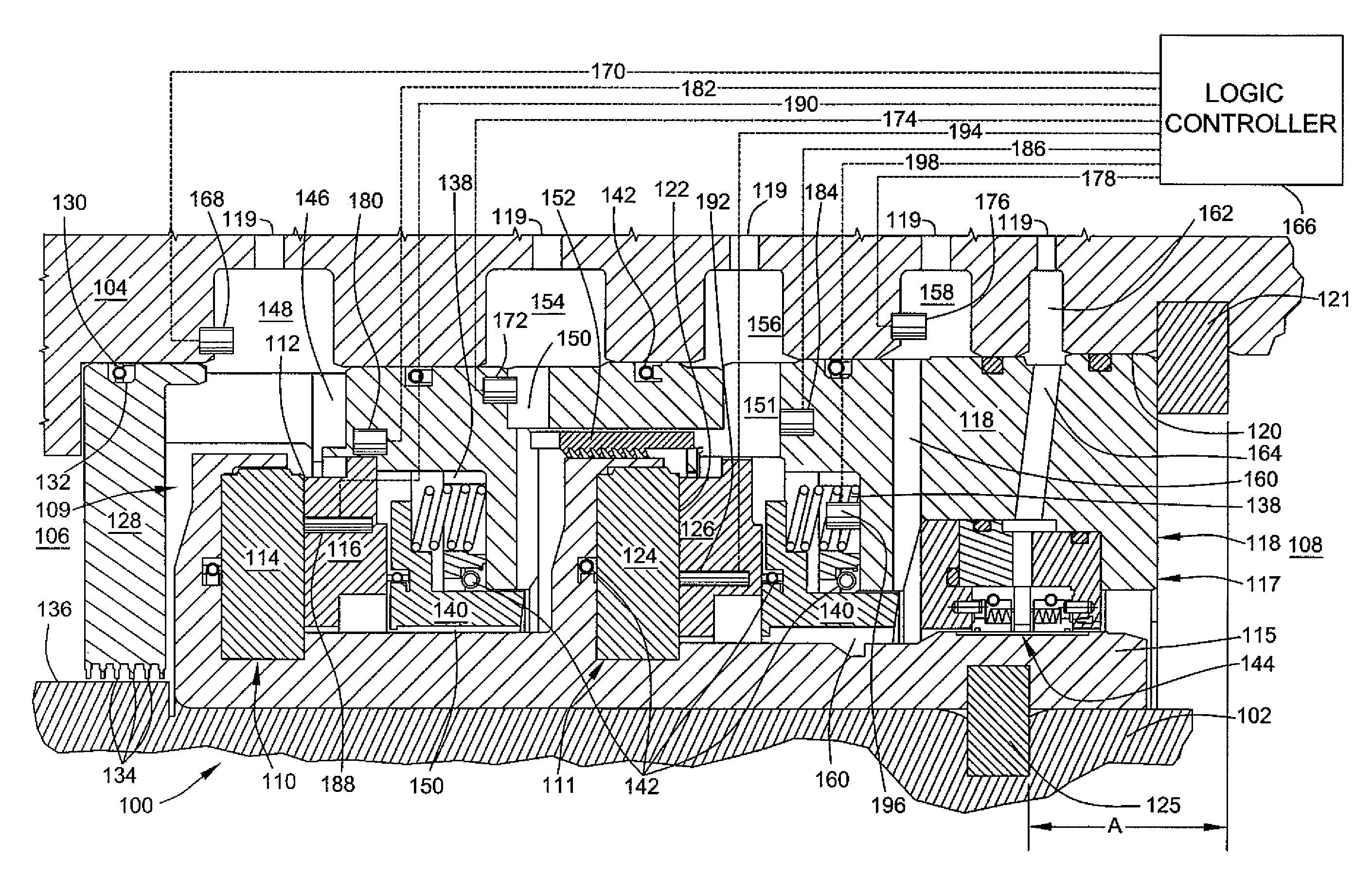
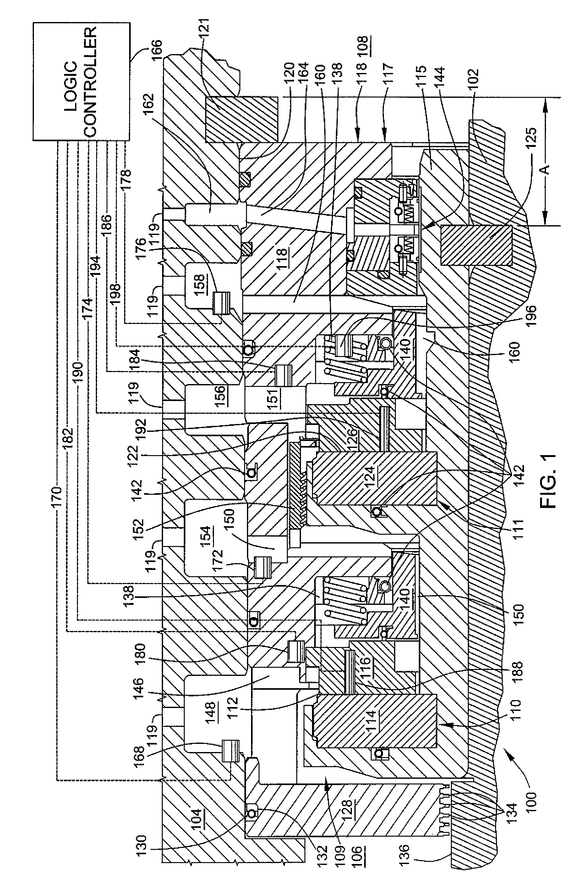
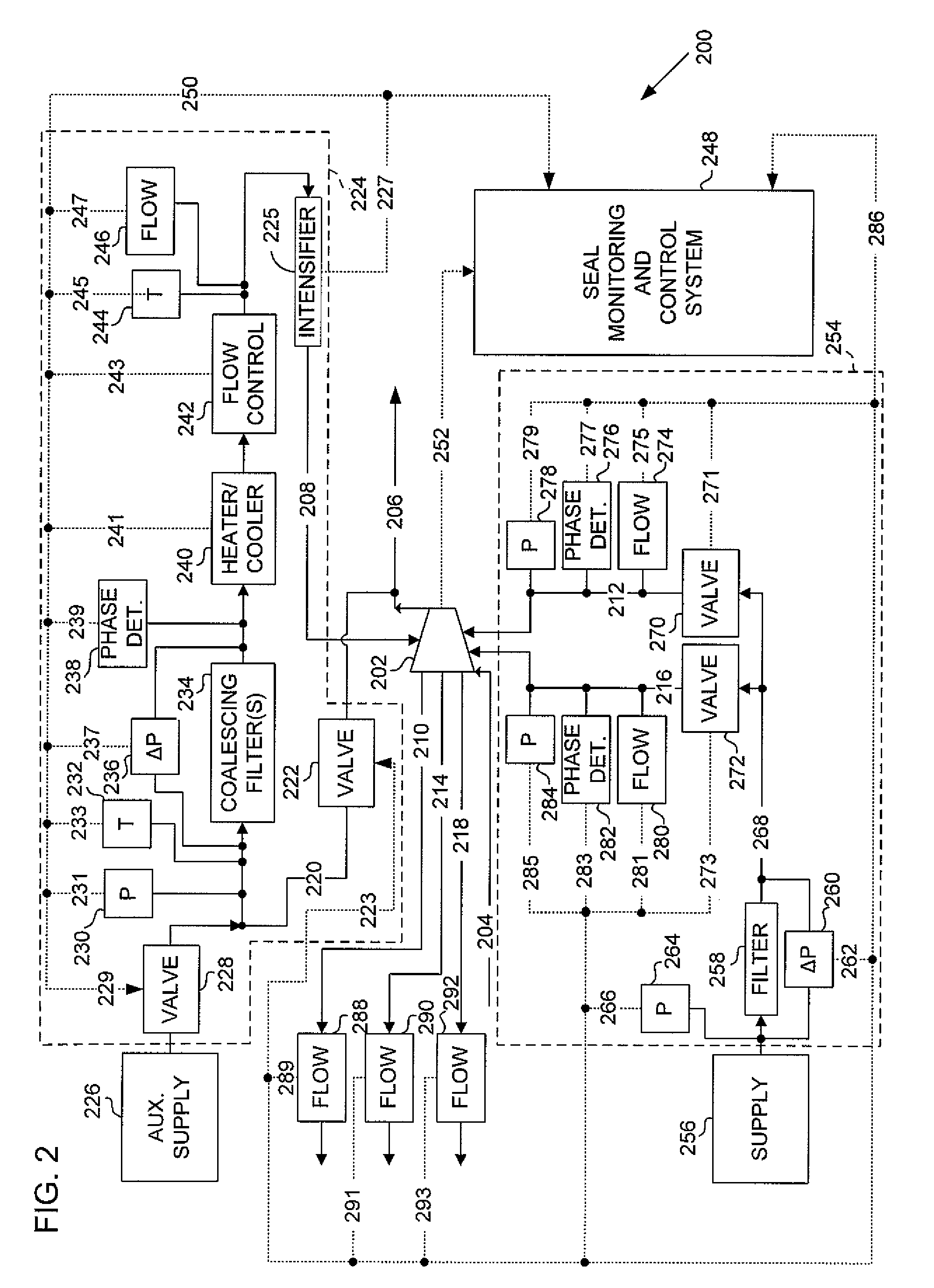
[0019]Non-contacting dry gas seals, such as those commonly applied to gas compressors, include a single, tandem, or double seal arrangements. In a typical installation, gas conditioning equipment is often arranged in modular form, and gas supply controls are typically arranged in a gas control panel. Such combinations are employed for both overhung and beam compressors. While one combination that includes a tandem non-contacting dry gas seal for a compressor that is part of an installation having gas conditioning equipment and gas supply controls arranged in a control panel is used in the description of the embodiments that follow, but one can appreciate that the principles and methods disclosed herein are applicable to other structural combinations, and / or seal configurations. As is well known, the associated gas control panel is arranged and piped into the system to control treated seal gas supplied from the process source. It also receives gas from the leakage ports. Appropriate ...
PUM
 Abstract
Description
Claims
Application Information