
Rotary adjustment for dual switch assembly

a dual switch and adjustment technology, applied in the direction of frequency-division multiplex, switch power arrangement, instruments, etc., can solve the problems of cost and complexity, diaphragm and tongue approach also adds parts, and is typically very time-consuming to adjust, and the method of changing the relative height of the switch can also be time-consuming

Active Publication Date: 2014-02-18
ASHCROFT
View PDF16 Cites 3 Cited by
  • Summary
  • Abstract
  • Description
  • Claims
  • Application Information

AI Technical Summary

Benefits of technology

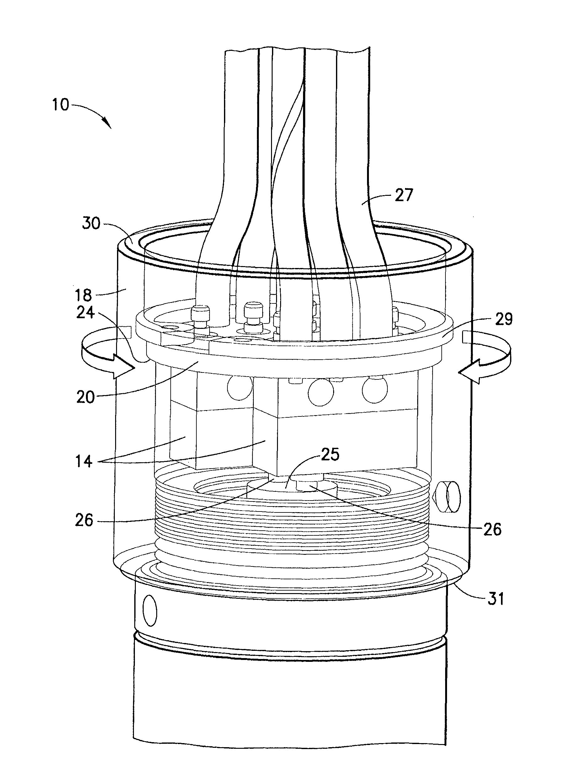
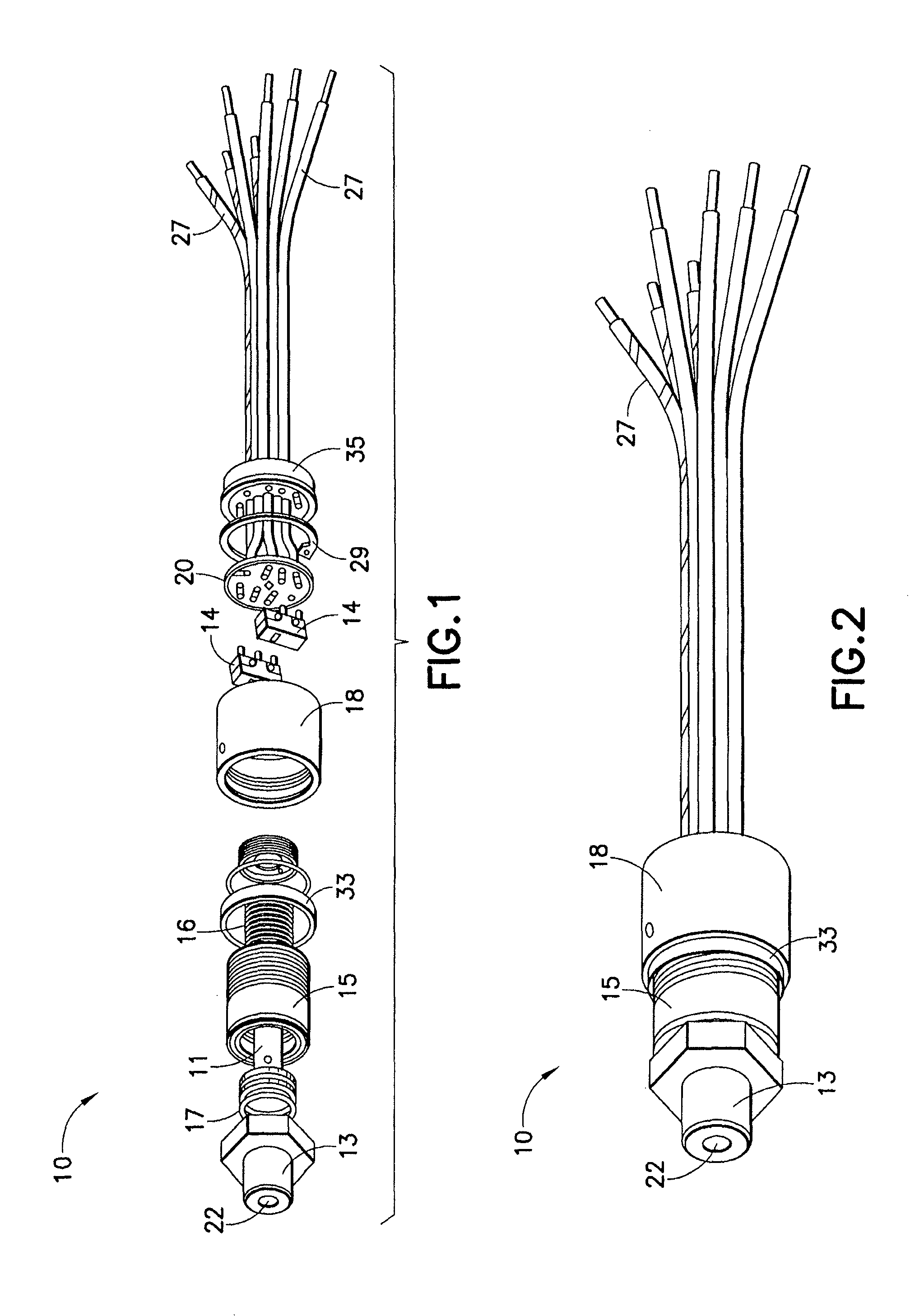
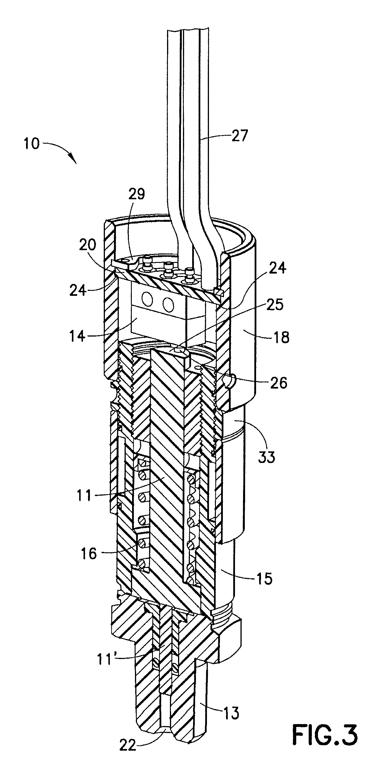
The present invention provides a sensing device with a variable height switch actuator. The device includes two housings, one for housing the sensing element and another for housing the electrical mounting member. The electrical mounting member has a switch actuator that can be adjusted in height relative to the sensing element by rotating the housing. The device also has a groove that is angled with respect to the housing and travels approximately 360 degrees around its inner portion. The actuatable sensing element is sensitive to condition changes and the rotation of the electrical mounting member allows the user to adjust the position of the switch actuators so that they change state at the same time upon actuation of the sensing element. The technical effect of this invention is to provide a sensing device with a variable height switch actuator that is easy to use and flexible in response to different conditions.

Problems solved by technology

However, the Belleville design adds several parts and therefore cost and complexity.
The diaphragm and tongue approach also adds parts and is typically very time consuming to adjust.
Other conventional methods of changing the relative heights of the switches can also be time consuming and add cost / complexity to the devices.

Method used


Image

  • Rotary adjustment for dual switch assembly
  • Rotary adjustment for dual switch assembly
  • Rotary adjustment for dual switch assembly

Examples


Embodiment Construction

[0033]In the description which follows, like parts are marked throughout the specification and drawings with the same reference numerals, respectively. Drawing figures are not necessarily to scale and in certain views, parts may have been exaggerated for purposes of clarity.

[0034]The present disclosure provides for improved systems and methods for fabricating sensing and / or control device assemblies, e.g., a dual pressure switch sensing / control device, a dual temperature switch sensing / control device or the like. More particularly, the present disclosure provides for systems and methods for fabricating sensing / control device assemblies (e.g., dual switch sensing / control device assemblies) with improved adjustment features and / or functionalities for switch calibration and / or adjustment. In an exemplary embodiment, the present disclosure provides for systems and methods for fabricating sensing / control device assemblies (e.g., dual switch sensing / control device assemblies) with advanta...


PUM


Abstract

The present disclosure provides for systems and methods for fabricating sensing and / or control device assemblies, e.g., a dual pressure switch sensing and / or control device, a dual temperature switch sensing and / or control device or the like. More particularly, the present disclosure provides for systems and methods for fabricating sensing and / or control device assemblies (e.g., dual switch sensing and / or control device assemblies) with adjustment features and / or functionalities for switch calibration and / or adjustment. In one embodiment, the present disclosure provides for systems and methods for fabricating sensing and / or control device assemblies (e.g., dual switch sensing and / or control device assemblies) with rotary adjustment features / functionalities wherein the switches of the sensing device may be calibrated or adjusted via the rotary adjustment features / functionalities.

Description

BACKGROUND[0001]1. Technical Field[0002]The present disclosure relates to a sensing and / or control device assembly and method for fabricating sensing / control device assemblies and, more particularly, to sensing / control device assemblies (e.g., dual switch sensing / control device assemblies) with adjustment features and / or functionalities (e.g. rotary adjustment features / functionalities) for switch calibration and / or adjustment.[0003]2. Background Art[0004]Sensing and / or control devices, such as pressure switches or temperature switches, have innumerable uses in industry. For example, pressure or temperature switches to sense or detect when a specified pressure or temperature has been reached in a process media, device or system are well known. Sensing / control devices are useful in a myriad of different environments for commercial and industrial applications. Typically, a pressure or temperature switch is an electrical switch that is responsive to pressure or temperature changes.[0005...

Claims


Application Information

Patent Timeline
Patent Type & Authority Patents(United States)
IPC IPC(8): H01H35/26
CPCH01H35/38H01H35/2628
Inventor BESSETTE, TYLERDLUGOS, DAVID
Owner ASHCROFT
Learn More