Method and system for cooling heat-generating component in a closed-loop system

a closed-loop system and heat-generating component technology, applied in the field of closed-loop cooling systems, can solve the problems of degrading or completely ruining the performance of the heat-generating component, not being able to cool to the desired level, and pressure differential switches of the type used in these types of cooling systems of the past and described

Inactive Publication Date: 2002-09-05
TARK
View PDF0 Cites 55 Cited by
  • Summary
  • Abstract
  • Description
  • Claims
  • Application Information

AI Technical Summary

Problems solved by technology

The increase in temperature of the fluid could also result in the heat-generating component not being cooled to the desired level.
This could either degrade or completely ruin the performance of the heat-generating component altogether.
Unfortunately, the pressure differential switch of the type used in these types of cooling systems of the past and described earlier herein are expensive and require additional care when coupling to the venturi.
The pressure differential switches of the past were certainly more expensive than a conventional pressure switch which simply monitors a pressure at a given point in a conduit in the closed-loop system.
Another problem with the venturis of the past is that they were typically situated in line in a cooling system which caused the overall dimensions of the cooling system or portion thereof to increase because of the axial length of the venturi.

Method used


Image

  • Method and system for cooling heat-generating component in a closed-loop system
  • Method and system for cooling heat-generating component in a closed-loop system
  • Method and system for cooling heat-generating component in a closed-loop system

Examples


second embodiment

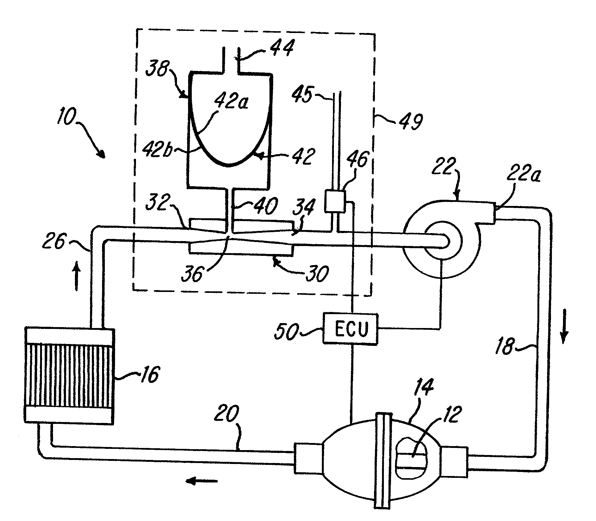
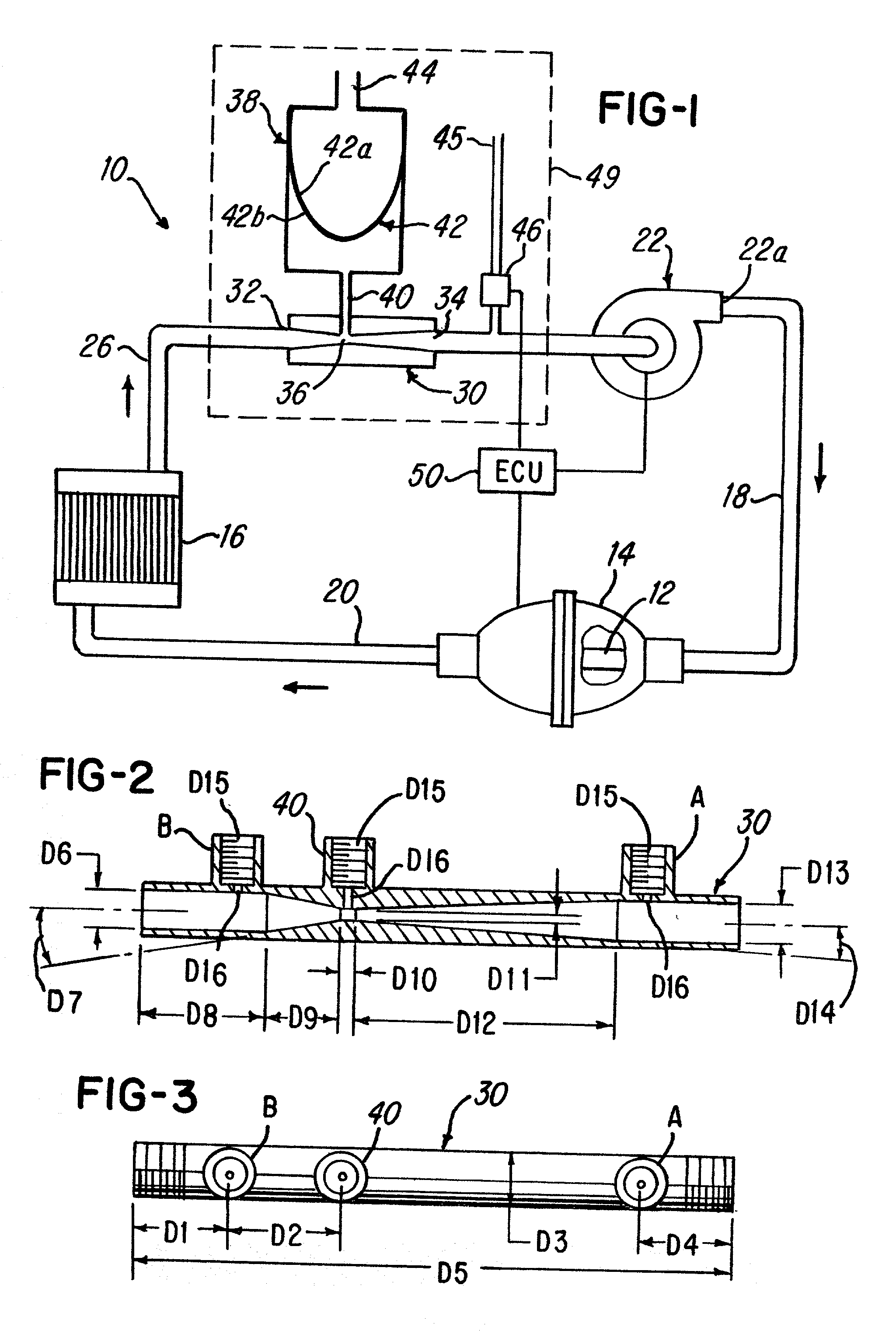
[0083] Advantageously, providing a circular venturi having a venturi passageway of flow path that flows about an axis of the pump 101' provides a convenient means and method for reducing the overall space requirements of the pump 101' and the venturi 105' because the length of the venturi 105' is reduced. Thus, note the axial dimension of F4 (FIG. 13) of venturi 105' of the second embodiment is considerably shorter than the axial dimension D5 (FIG. 3). This makes the circular venturi 105' advantageous when axial space requirements of the system 10' are a concern.

first embodiment

[0084] While the method herein described, and the form of apparatus for carrying this method into effect, constitute preferred embodiments of this invention, it is to be understood that the invention is not limited to this precise method and form of apparatus, and that changes may be made in either without departing from the scope of the invention, which is defined in the appended claims. For example, while the systems 10 and 10' have been shown and described for use relative to an X-ray cooling system of the type used in, for example, CT Scanners, Diagnostic X-Ray tube used in "C"-Arms, and industrial X-Ray tubes used in non-destructive testing and bomb scanners, it is envisioned that the systems 10 and 10' may be used with an internal combustion engine, cooling system, a hydronic boiler or any closed loop heat exchanger that uses a fluid to cool another fluid. The embodiments illustrated in FIGS. 1-6 and 8-13, may be used with the system 100 illustrated in FIG. 7. As illustrated i...


PUM


Abstract

A system and method for improving cooling of a heat-generating component in a closed-loop cooling system is shown. The system comprises a venturi having a throat which is coupled to an expansion tank that is exposed to atmospheric pressure in the embodiment being described. The venturi, when used with a pressure switch, can operate to determine a flow rate which can be used to generate a signal which in turn is used to activate or deactivate one or more of the components, such as the heat-generating component, in the system. Also shown is another embodiment wherein a circular venturi is provided to permit a venturi passageway to be defined about an axis of the pump in order to shorten the overall length of the pump and venturi combination.

Description

[0001] This application is a continuation-in-part of U.S. patent application Ser. No. 09 / 745,588 filed Dec. 12, 2000.[0002] 1. Field of the Invention[0003] This invention relates to a cooling system, and more particularly, it relates to a venturi used in a closed-loop cooling system to facilitate cooling a heat-generating component by raising the pressure of the fluid in the system and, therefore, the boiling point of the fluid, with the increased pressure establishing that there is flow in the closed-loop system.[0004] 2. Description of the Prior Art[0005] In many prior art cooling systems, the fluid is absorbing heat from a heat-generating component. The fluid is conveyed to a heat exchanger, which dissipates the heat, and the fluid is then recirculated to the heat-generating component. The size of the heat exchanger is directly related to the amount of heat dissipation required. For example, in a typical X-ray system, an X-ray tube generates a tremendous amount of heat on the ord...

Claims


Application Information

Patent Timeline
Patent Type & Authority Applications(United States)
IPC IPC(8): F25B1/06
CPCF25B1/06F25B2500/01
Inventor MCCARTHY, JOSEPH H. JR.PHAM, HOA DAO
Owner TARK
Why Eureka
Try Eureka