Split Cooling Method and Apparatus

a cooling method and apparatus technology, applied in the direction of engine cooling apparatus, liquid cooling, combustion engines, etc., can solve the problem of not allowing flexibility to provide a lower coolant temperatur

Active Publication Date: 2012-09-20
NORFOLK SOUTHERN
View PDF7 Cites 23 Cited by
  • Summary
  • Abstract
  • Description
  • Claims
  • Application Information

AI Technical Summary

Problems solved by technology

These traditional cooling systems of the prior art have a disadvantage because these sy...

Method used


Image

  • Split Cooling Method and Apparatus
  • Split Cooling Method and Apparatus
  • Split Cooling Method and Apparatus

Examples


Embodiment Construction

[0016]The present application is directed toward the technical field of cooling systems for diesel engines utilizing multiple flow paths to provide flexibility efficiency, and reduced emissions.

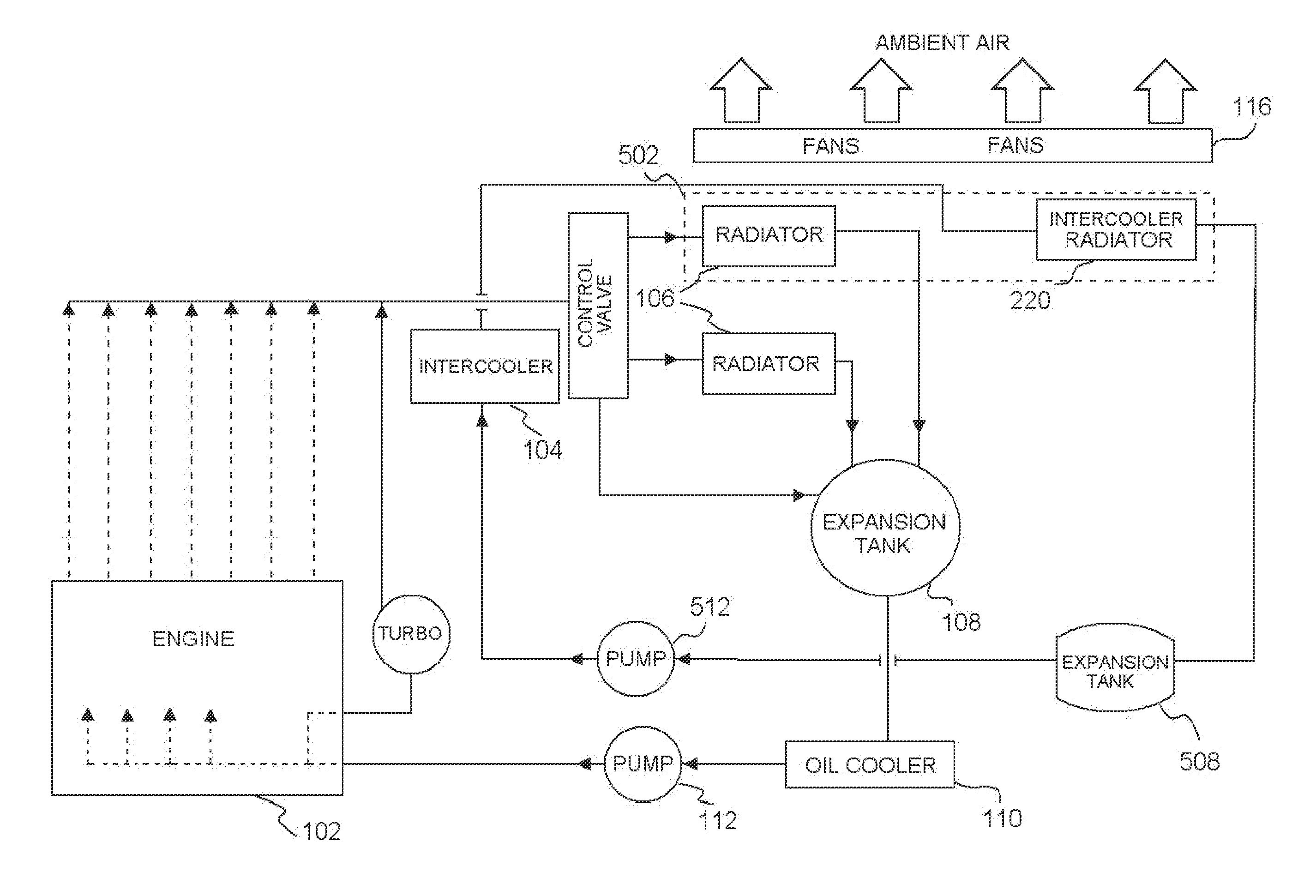
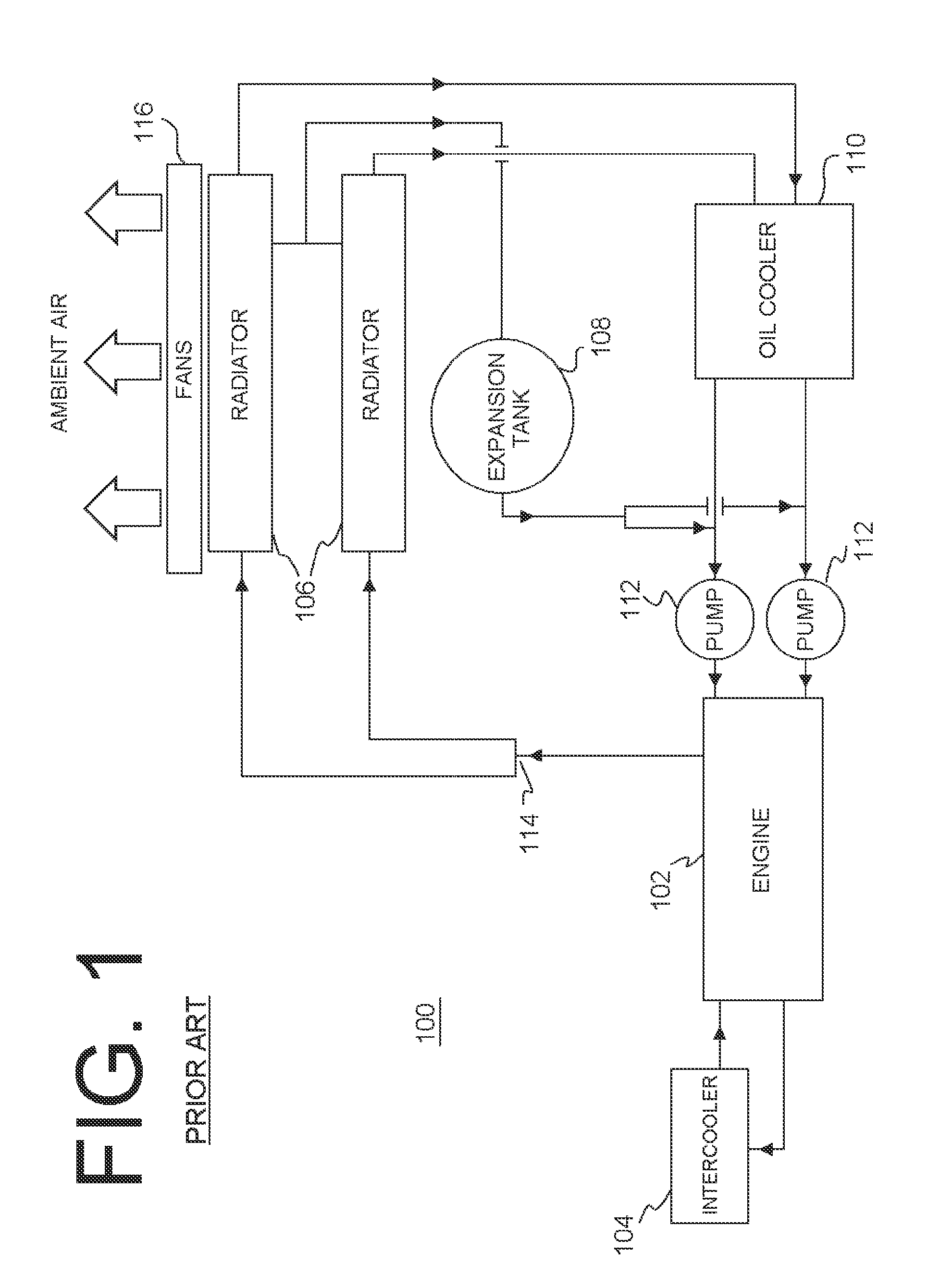
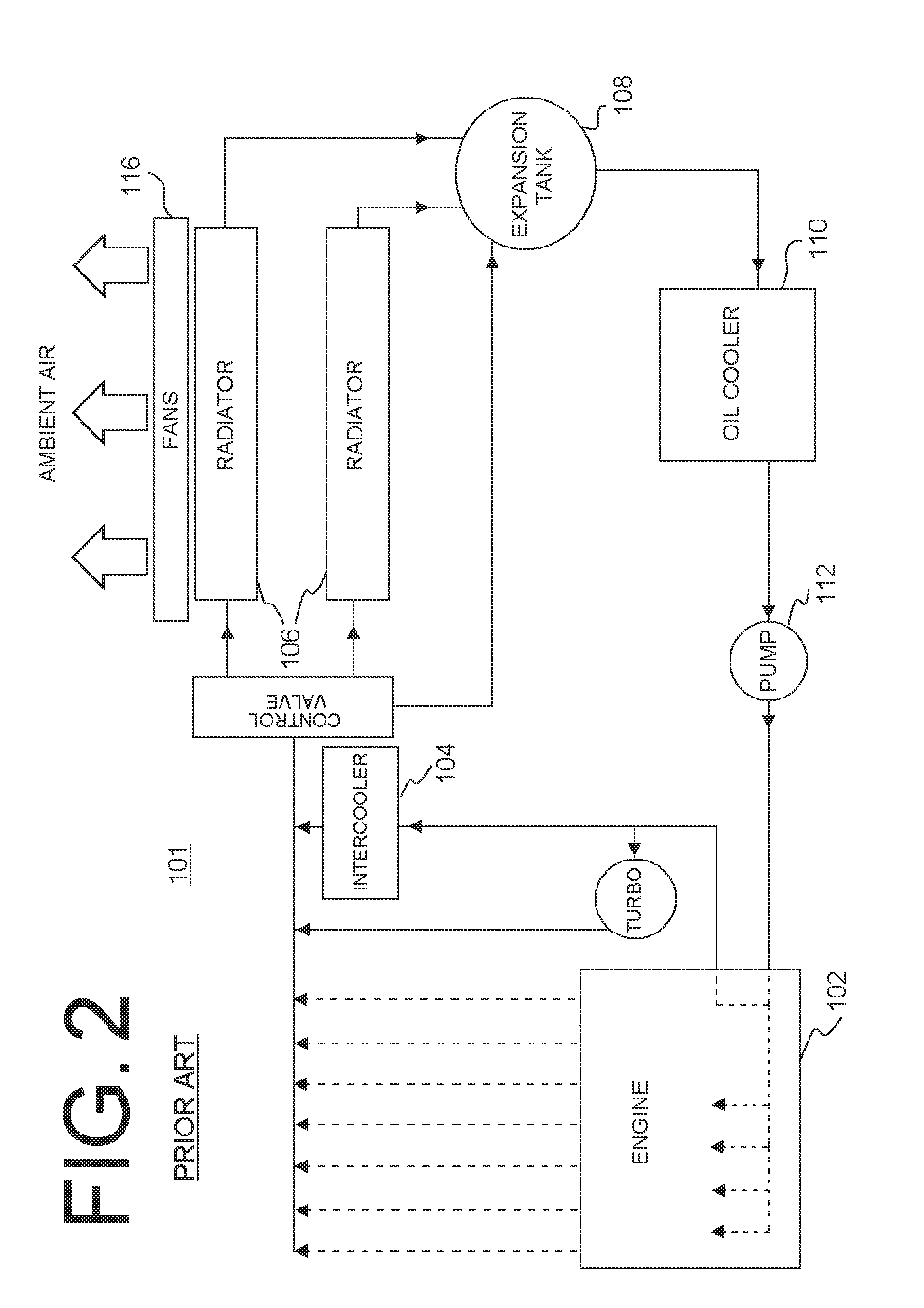
[0017]Referring to FIG. 1, a typical prior art cooling system 100 is depicted. Cooling system 100 may include an engine 102, at least one intercooler 104, at least one radiator 106, an expansion tank 108, an oil cooler 110, and at least one pump 112. Cooling system 100 is generally utilized to maintain certain optimal temperatures of various components in cooling system 100 by circulating a liquid coolant, such as water that may include chemical additives such as anti-freeze and corrosion inhibitors. Cooling system 100 also includes piping for interconnecting the various components of the system and associated valves, as will be described more fully below.

[0018]Engine 102 includes internally formed cooling passages and / or a water jacket through which the some of the liquid coolant flows and a...


PUM


Abstract

A system and method for cooling an internal combustion engine. In one embodiment of the invention a cooling system for an internal combustion engine is disclosed, comprising an engine; an intercooler for receiving combustion air from a turbocharger, the intercooler comprising an air-to-liquid heat exchanger for exchanging heat between the combustion air and a liquid coolant; an intercooler radiator; at least one engine coolant radiator; an expansion tank; an oil cooler; and at least one pump, wherein the dedicated fan is controlled by a temperature switch or controller and wherein the at least one engine coolant radiator and the intercooler radiator are located on opposite sides of the engine.

Description

TECHNICAL FIELD[0001]The present invention is in the field of locomotive diesel engines and cooling systems. More particularly, the present invention is in the technical field of cooling systems for diesel engines utilizing multiple flow paths to provide flexibility, efficiency and reduced emissions.BACKGROUND OF THE INVENTION[0002]Cooling systems for internal combustion engines, such as those powering locomotives, are known in the art for the purpose of maintaining engine temperature and lubricating oil temperatures within desired operating parameters. In addition, the cooling system is used to reduce the temperature of the charge air. In typical cooling systems, ambient air is forced through heat exchangers and the cooling capability is constrained by the temperature of the ambient air as well as other factors. There are two common types of cooling systems commonly found in locomotives.[0003]For example, the first type of cooling system consists of a Y-shaped pipe on the engine wh...

Claims


Application Information

Patent Timeline
IPC IPC(8): F01P7/14F02B33/00
CPCF02B29/0406F01P2060/02F01P7/165F01P3/12
Inventor FAULKNER, DONALD R.THOMPSON, WILLIAM B.KEISTER, PATRICK E.MARTIN, ERIC C.MURRAY, CHARLES W.
Owner NORFOLK SOUTHERN
Why Eureka
Try Eureka