
Sterilization device for sterilization of lumen devices

a sterilization device and lumen technology, applied in the field of sterilization devices, can solve the problems of difficult penetration of the lumen (i.e., the interior passageway) with a gaseous sterilant, the limitations of the types of devices that can be sterilized, and the possibility of recontamination of the lumen

Active Publication Date: 2005-11-24
AMERICAN STERILIZER CO
View PDF4 Cites 23 Cited by
  • Summary
  • Abstract
  • Description
  • Claims
  • Application Information

AI Technical Summary

Benefits of technology

[0010] An advantage of the present invention is the provision of an apparatus for sterilizing a lumen device by drawing a gaseous sterilant through a lumen.
[0011] A still further advantage of the present invention is the provision of an apparatus that generates a turbulent flow to mix gaseous sterilant with unsterile air.
[0012] A still further advantage of the present invention is the provision of an apparatus for sterilizing a lumen device that exposes unsterile air within an expansion tank to a gaseous sterilant.
[0013] A still further advantage of the present invention is the provision of an apparatus for sterilizing a lumen device that exposes unsterile air within a lumen to a gaseous sterilant.
[0014] These and other advantages will become apparent from the following description of a preferred embodiment taken together with the accompanying drawings and the appended claims.

Problems solved by technology

However, the length of a lumen is many times greater than its diameter and such geometry can make it difficult to penetrate the lumen (i.e., interior passageway) with a gaseous sterilant.
Such drawbacks include complexity, limitations on the types of devices that can be sterilized, and possible recontamination of the lumen when the gaseous sterilant is withdrawn from the lumen.
Various problems may be encountered when using prior art expansion tanks to sterilize lumen devices.
One problem is inadequate sterilization caused by the presence of unsterile air within the expansion tank and the lumen.
In this regard, some unsterile air may remain within the lumen after a vacuum has been drawn on the sterilization chamber.
The unsterile air poses a problem because it does not actively mix with the gaseous sterilant, due to nonturbulent flow (i.e., plug flow).
However, gas diffusion is a slow process, and does not insure that all contaminates are adequately exposed to the gaseous sterilant.

Method used


Image

  • Sterilization device for sterilization of lumen devices
  • Sterilization device for sterilization of lumen devices
  • Sterilization device for sterilization of lumen devices

Examples


Embodiment Construction

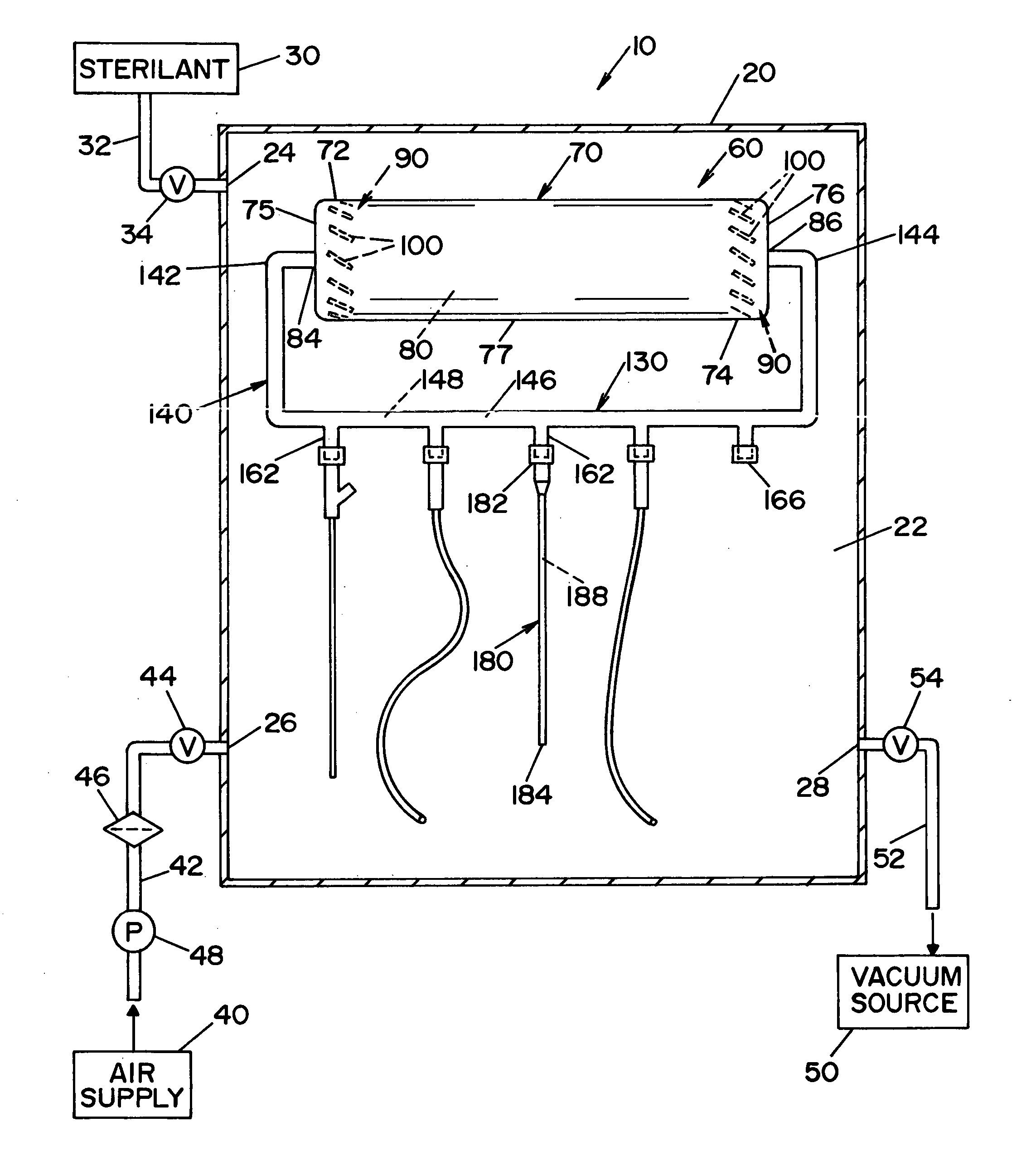
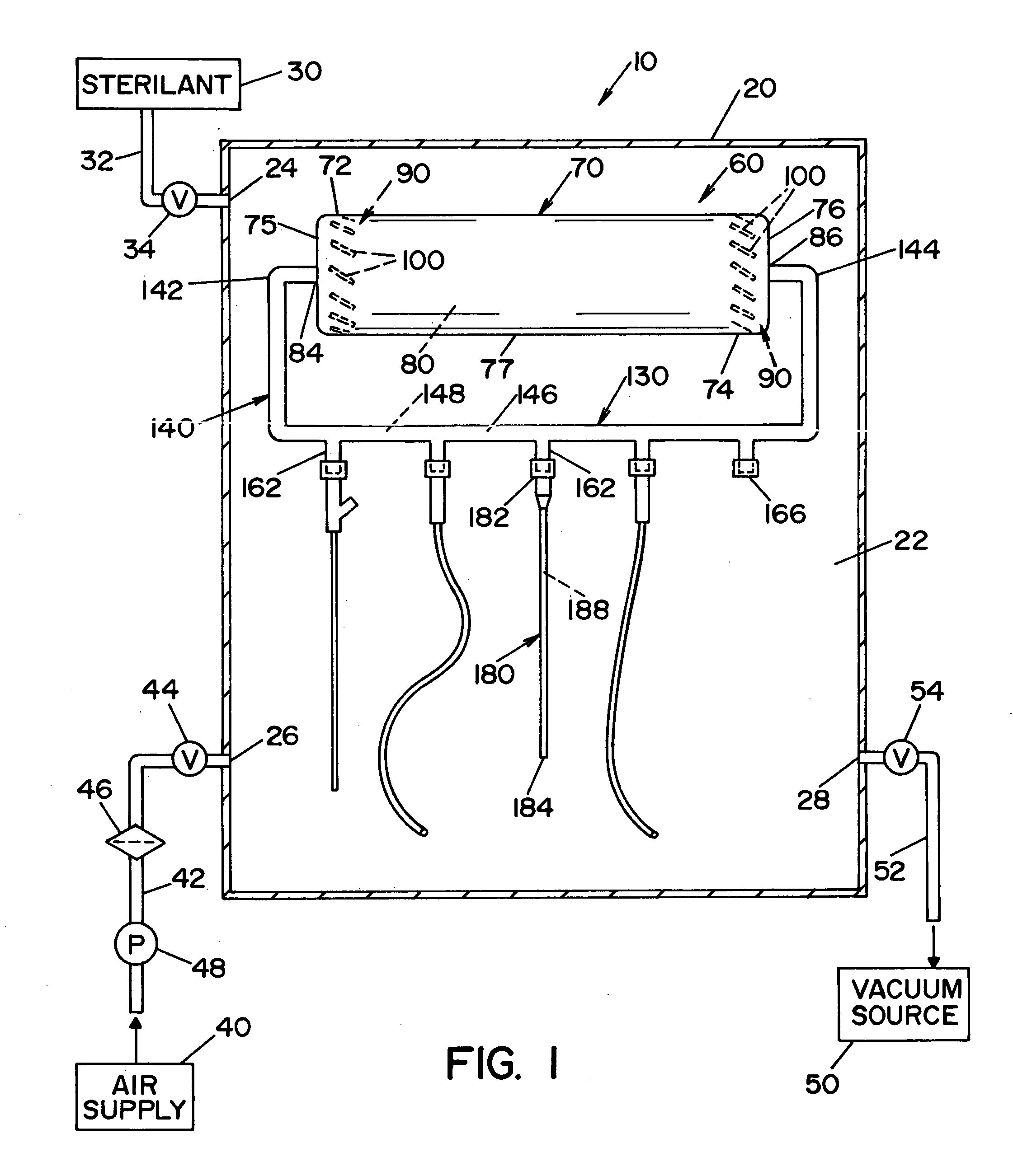
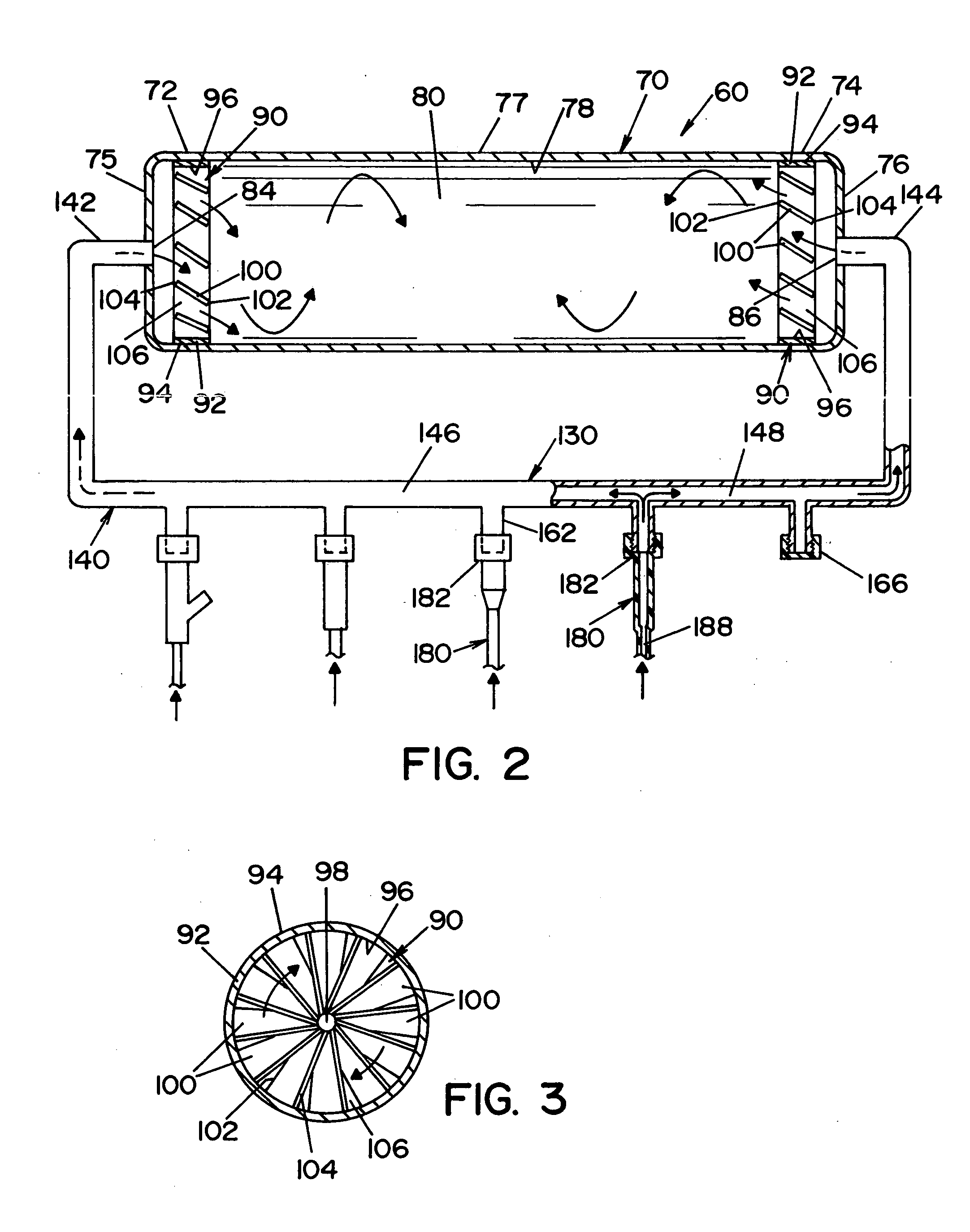
[0019] Referring now to the drawings wherein the showings are for the purposes of illustrating a preferred embodiment of the invention only and not for purposes of limiting same, FIG. 1 shows a sterilization apparatus 10 illustrating a preferred embodiment of the present invention. In the embodiment shown, sterilization apparatus 10 is generally comprised of a housing 20, an expansion tank assembly 60, and at least one mixing member 90.

[0020] Housing 20 defines a treatment chamber 22. In the illustrated embodiment, housing 20 has a first input port 24, a second input port 26, and an output port 28. A first conduit 32 fluidly connects first input port 24 of housing 20 with a sterilant supply 30. In a preferred embodiment, sterilant supply 30 provides a source of at least one gaseous / vaporous sterilant (hereinafter, gaseous sterilant) including, but not limited to, vaporized hydrogen peroxide (VHP), ozone, ethylene dioxide, and chlorine dioxide. A first valve 34 is disposed along fir...


PUM


Abstract

An apparatus for the sterilization of lumen devices. The apparatus for sterilizing lumen devices is comprised of a chamber defining a region for sterilization, an expansion tank assembly, and a mixing member. The chamber is adapted to receive the expansion tank. The expansion tank is adapted to fluidly connect to at least one lumen device. The mixing member is disposed within the expansion tank to mix gaseous sterilant within residual gas that may include contaminants.

Description

FIELD OF THE INVENTION [0001] The present invention relates to sterilizers and the like, and more particularly to a sterilization device for sterilizing lumen devices with a gaseous chemical. BACKGROUND OF THE INVENTION [0002] Various systems and apparatus have been developed to sterilize lumen devices, such as endoscopes and other devices having a lumen. Methods of sterilizing lumen devices may utilize a sterilization chamber and one or more gaseous sterilants, such as ozone or vaporized hydrogen peroxide (VHP). In order to achieve effective sterilization, all contaminants within the lumen device must be exposed to the gaseous sterilant, including contaminants suspended in the air within the lumen device and contaminants on interior and exterior surfaces of the lumen device. However, the length of a lumen is many times greater than its diameter and such geometry can make it difficult to penetrate the lumen (i.e., interior passageway) with a gaseous sterilant. [0003] Known methods f...

Claims


Application Information

Patent Timeline
IPC IPC(8): A61B1/12A61L2/00A61L2/20
CPCA61B1/121A61L2202/122A61L2/208A61L2/206A61L2/20A61L2/00A61L2/16
Inventor WILLIAMS, KEVIN O.JUSTI, CHRISTOPHER J.
Owner AMERICAN STERILIZER CO
Learn More