Non-metallic expansion tank with internal diaphragm and clamping device for same

a non-metallic, expansion tank technology, applied in the field of water systems, can solve the problems of reducing heating efficiency, posing many problems to designers, and the likelihood of problems stemming from air and water interaction is grea

Active Publication Date: 2006-01-05
AMTROL LICENSING INC
View PDF4 Cites 23 Cited by
  • Summary
  • Abstract
  • Description
  • Claims
  • Application Information

AI Technical Summary

Benefits of technology

[0021] Preferably, the diaphragm comprises a resilient, non-porous material and / or an elastomeric material selected from a group comprising rubber, butyl rubber, thermoplastic, and elastomer plastic. More preferably, the diaphragm includes a bead portion comprising an annular ring that is convex on an inner side and concave on an outer side at its outer periphery. As a result, the bead portion of the diaphragm can be removably secured to the overlapable second end portion of the lower portion of the inner shell assembly to provide a watertight water portion in the lower portion.

Problems solved by technology

In any closed system containing air and water that undergoes natural or artificial temperature changes, the likelihood of problems stemming from interaction of air and water is great.
This poses many problems to designers.
First, air released by heated water, typically, accumulates in the compression tank and other portions of the heating system.
This accumulation results in reduced heating efficiency, often making continuous venting of radiators or convectors to bleed off the air necessary.
However, when the heated water reaches a desired temperature, the firing of the boiler ceases and the water begins to cool and contract.
Second, when a tank includes an air cushion, the cooling water may absorb all or substantially all of the air cushion, leaving a static water system.
Pressure pumps and surge chambers increase the cost of a water system.
This assembly is relatively expensive and labor and time intensive to manufacture.
Moreover, steel tanks can corrode from external environmental exposure, which can lead to deterioration of the tank assembly and the water system.
Such deterioration can lead to catastrophic results, such as leaking tanks.

Method used


Image

  • Non-metallic expansion tank with internal diaphragm and clamping device for same
  • Non-metallic expansion tank with internal diaphragm and clamping device for same
  • Non-metallic expansion tank with internal diaphragm and clamping device for same

Examples


Embodiment Construction

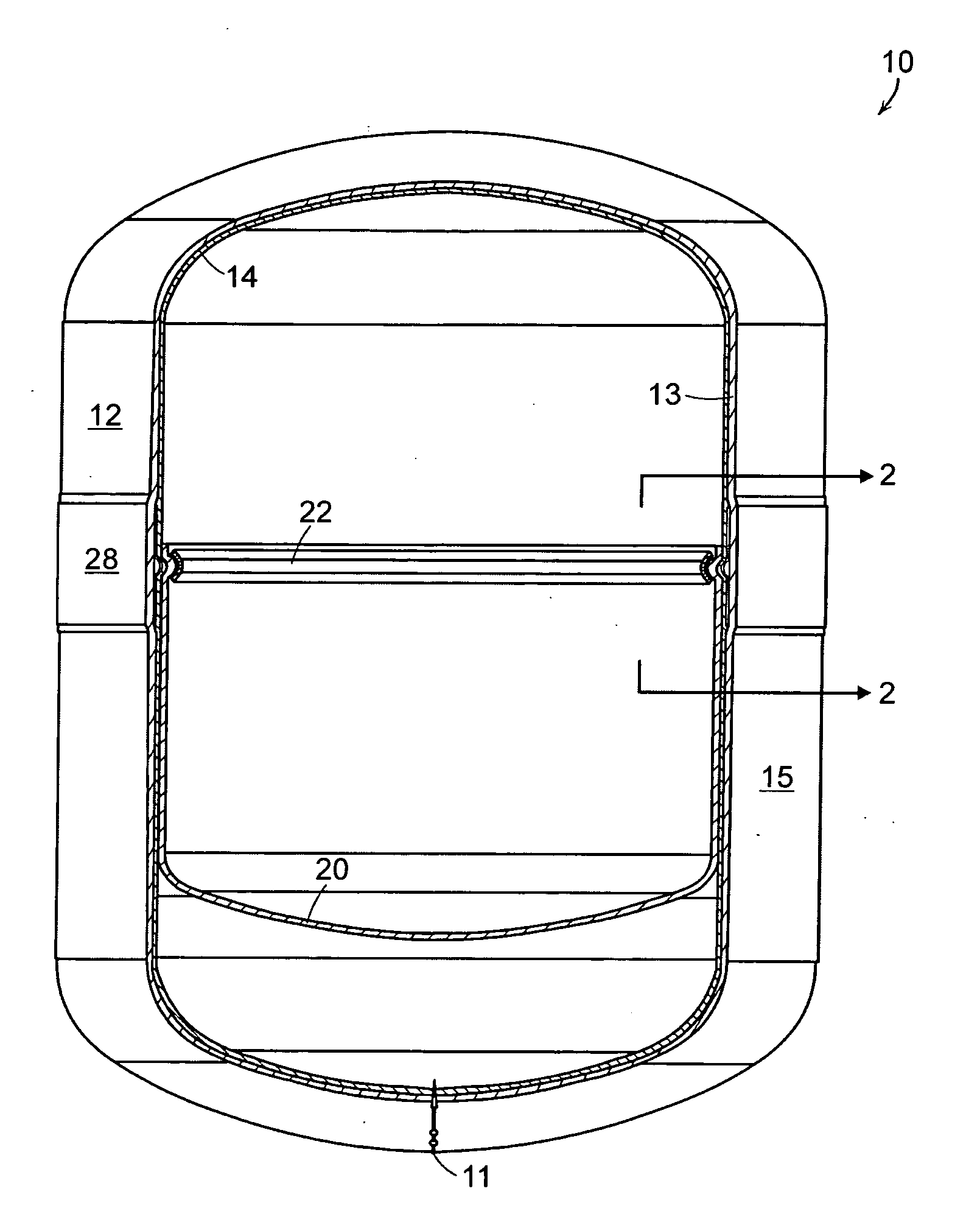
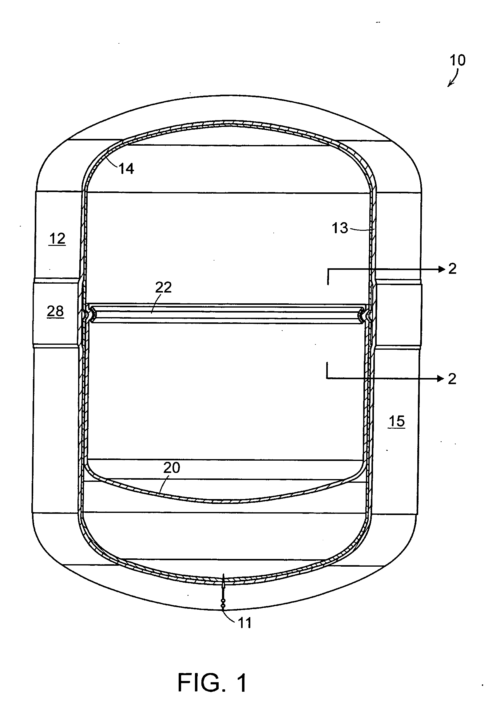
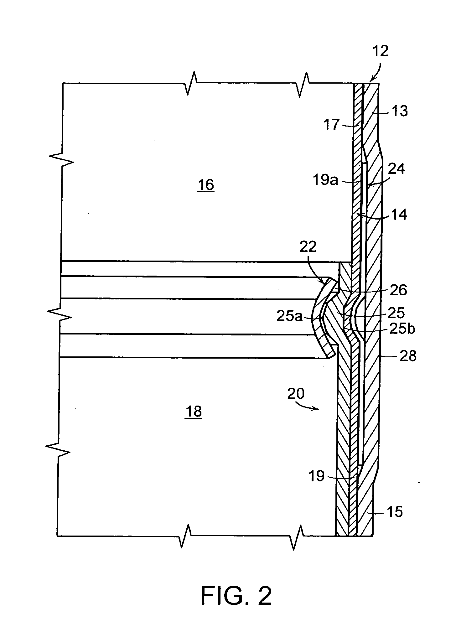
[0029] Referring now to the various figures of the drawings, wherein like reference characters refer to like parts, there is shown in FIGS. 1 and 2 an embodiment of a diaphragm-type tank assembly 10 in accordance with the present invention. The tank assembly 10 comprises an outer cylindrical housing or body 12 and an inner shell 14. The outer cylindrical body 12 is structured and arranged of a non-metallic material to provide structure and to protect the inner shell 14. The inner shell 14 is structured and arranged of a non-porous, non-metallic material, e.g., plastic, to provide a watertight water cell 18, or chamber, and an airtight pressurized gas cell 16, or chamber. A heavy gauge, non-porous, elastomeric diaphragm 20 is structured and arranged within the inner shell 14 to separate the water cell 18 and the pressurized gas cell 16.

[0030] Preferably, the outer cylindrical body 12 of the tank assembly 10 is made of fiber strands impregnated with a resin, e.g., an epoxy or thermop...


PUM


Abstract

A non-metallic, diaphragm-type tank assembly for use with a pressurized water system is disclosed. The tank assembly comprising a non-metallic outer body; a non-metallic inner shell assembly, including an upper portion and a lower portion, that is contained by the non-metallic outer body; and a diaphragm that is structured and arranged about the upper and lower portions of the inner shell assembly to separate said inner shell assembly into a water portion and a pressurized gas portion. Preferably, the diaphragm comprises a resilient, non-porous material and includes a bead portion comprising an annular ring that is convex on an inner side and concave on an outer side at its outer periphery. More preferably, the bead portion is removably secured to the overlapable end portion of the lower portion of the inner shell assembly by a clamping system that comprises an inner clamp hoop and an outer band. Specifically, the outer band can be mechanically crimped to compress and secure the second overlapable end portion and the bead portion of the diaphragm between the inner clamp hoop and the outer band to provide a watertight seal for the water portion.

Description

CROSS-REFERENCE TO RELATED APPLICATIONS [0001] This application claims the benefit of priority from U.S. provisional application No. 60 / 570,733, which was filed on May 12, 2004, the disclosure of which is hereby incorporated by reference in its entirety.FIELD OF INVENTION [0002] The present invention relates to water systems, e.g., closed hot water heating systems, pressurized water systems, and the like, that include expansion tanks or well tanks and, more particularly, to water systems including non-metallic expansion tanks with an internal diaphragm that separate air cells from water cells. DESCRIPTION OF THE RELATED ART [0003] Water systems that provide and distribute well water domestically in rural parts of the country typically include a pump to draw water from the well; pipes or other conduits through which water travels; and a tank for storing water, e.g., a well tank. Well tanks, e.g., expansion tanks, are structured and arranged to store water until demanded and to accomm...

Claims


Application Information

Patent Timeline
Patent Type & Authority Applications(United States)
IPC IPC(8): B65D1/32F24D3/10
CPCF24D3/1016F24D3/1008
Inventor GREMOUR, NICHOLAS C.VAN HAAREN, CHRISTOPHER A.
Owner AMTROL LICENSING INC
Why Eureka
Try Eureka