Sliding stage cementing tool

a cementing tool and sliding stage technology, applied in the direction of fluid removal, sealing/packing, borehole/well accessories, etc., can solve the problems of loss in formation, inability to cement the entire well, and inability to complete the single stage cement injection process

Active Publication Date: 2014-02-25
SAUDI ARABIAN OIL CO
View PDF6 Cites 10 Cited by
  • Summary
  • Abstract
  • Description
  • Claims
  • Application Information

AI Technical Summary

Problems solved by technology

However, as wells are increasingly being drilled deeper, the hydraulics for cementing the casing wellbore annulus in a substantially deep well makes the single stage cement injection process impracticable.
Also, in some instances it is impossible to cement the entire well.
For example, cement is not provided in portions of the well, where the well formation pressure is less than well hydrostatic pressure, or where the formation is too porous so high cement slurry pressure in the case induces formation breakdown, which leads to losses in the formation, as a result, no cement is present.
However, presently known tools experience failures such as failure to inflate the packer element, failure to open ports, failure to close ports, and disconnection of the tool from the casing string.

Method used


Image

  • Sliding stage cementing tool
  • Sliding stage cementing tool
  • Sliding stage cementing tool

Examples


Embodiment Construction

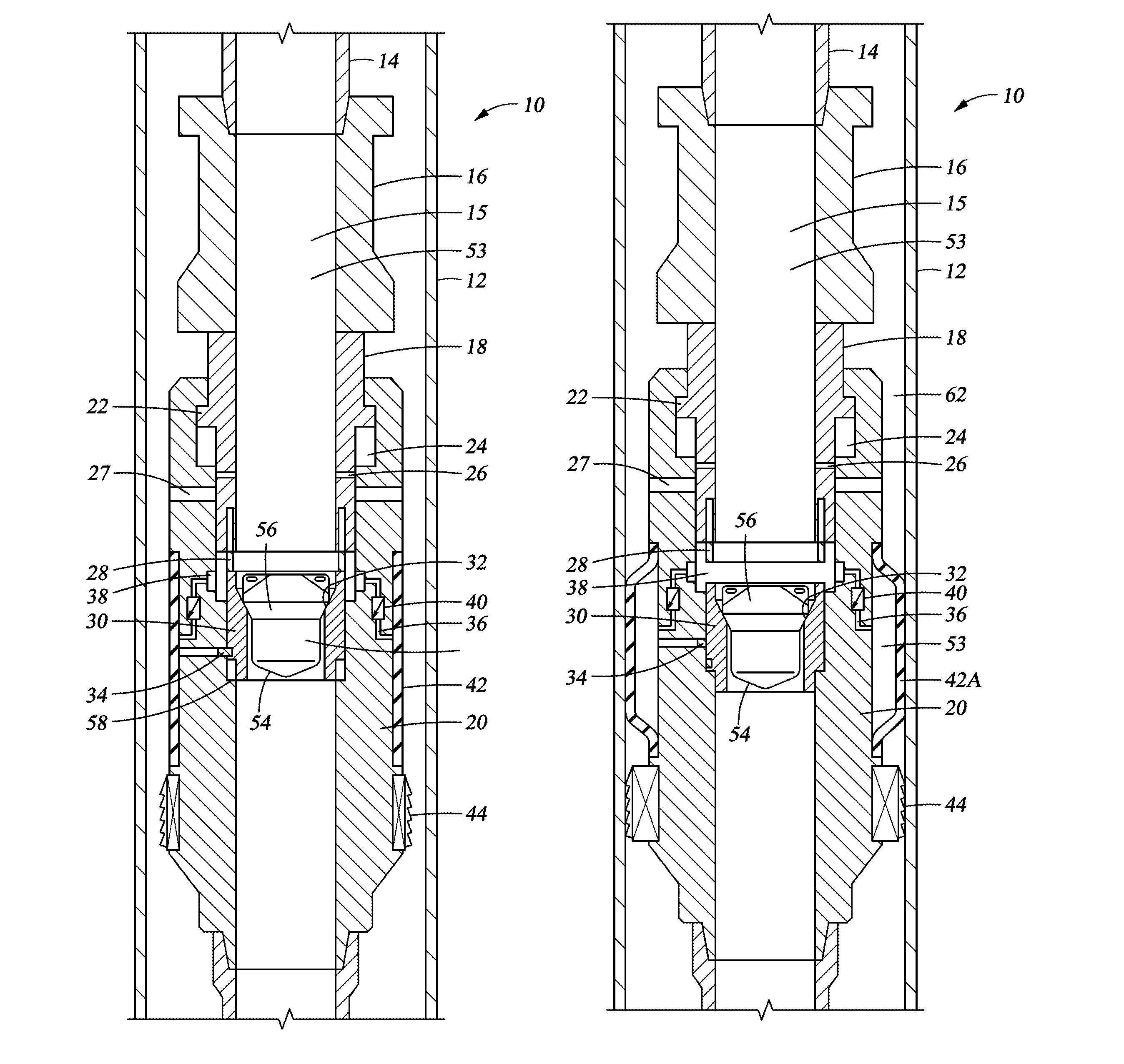
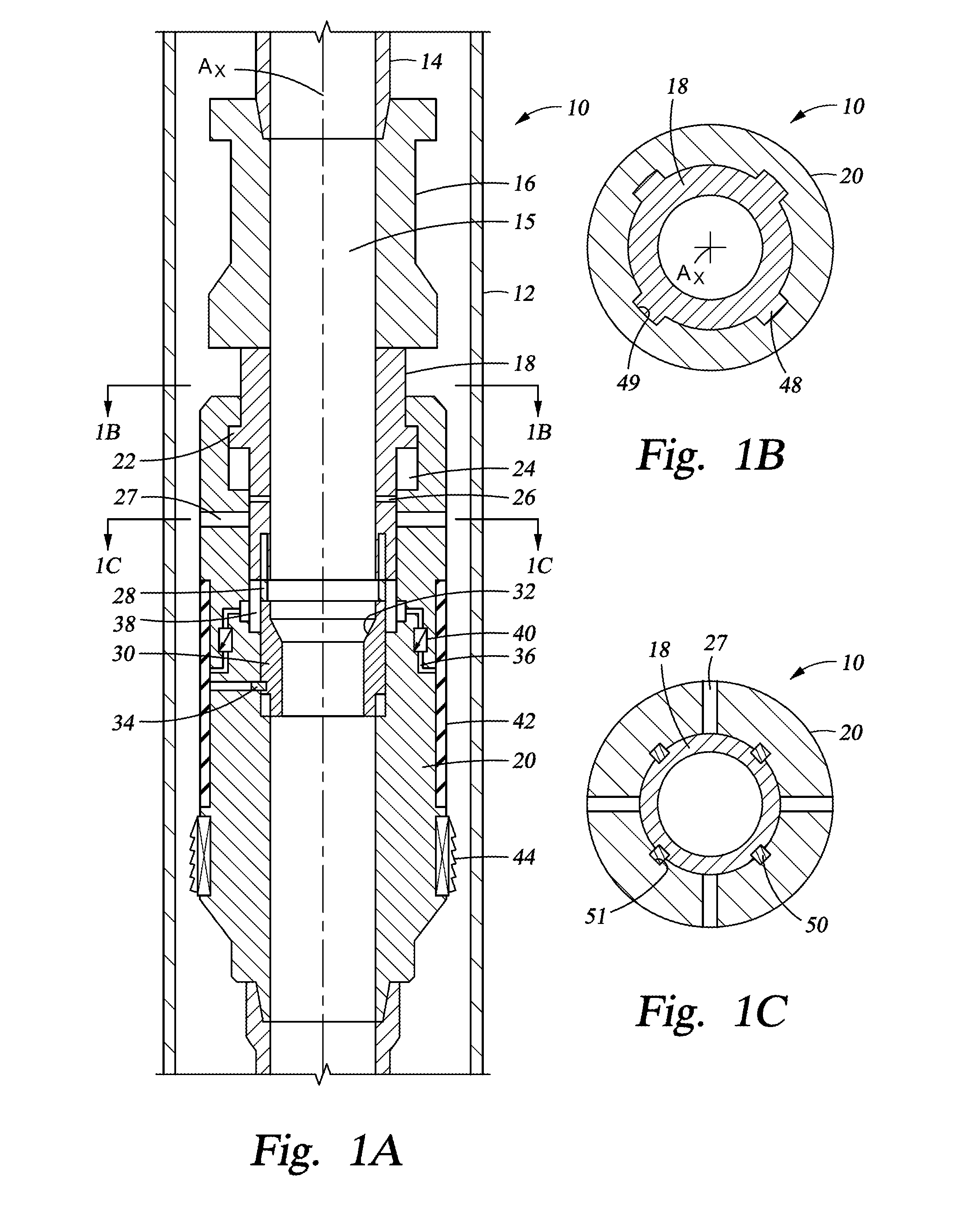
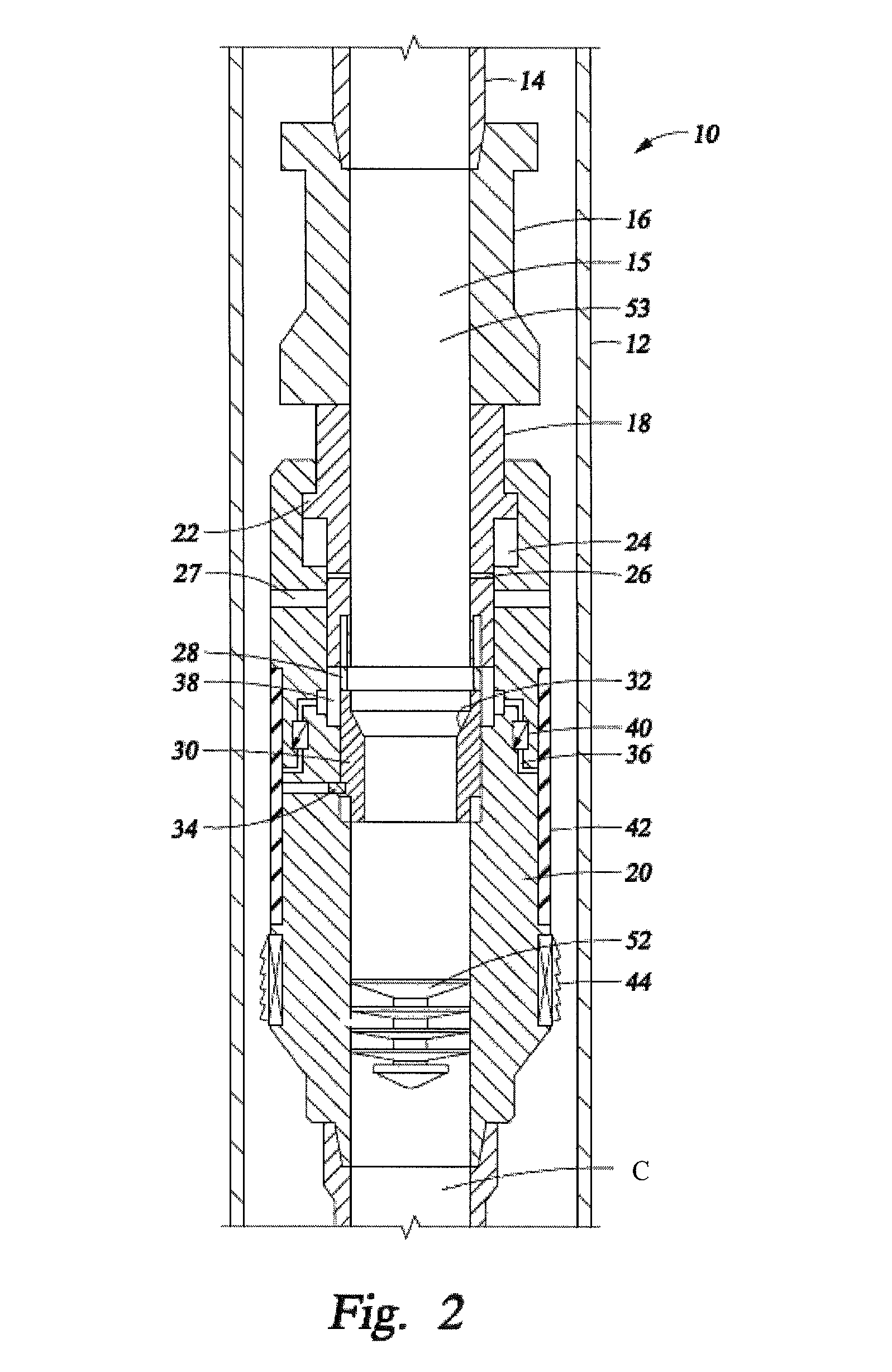
[0019]An example embodiment of a sliding stage cementing tool 10 is shown in a side sectional view in FIG. 1A inserted within a string of outer casing 12. The cementing tool 10 is deployed integral within an inner casing string 14 shown connected to the cementing tool 10 with a threaded connection. An axial bore 15 extends through the tool 10 so that anything flowing through the casing string 14 thereby flows through the cementing tool 10. An annular casing box 16 is provided on an upper end of the cementing tool 10 and is where the casing string 14 attaches to the cementing tool 10. An optional flange is provided on an upper end of the casing box 16 that circumscribes the threaded connection between the cementing tool 10 and casing string 14. The lower end of the casing box 16 is provided with a shoulder that slopes radially outward from a reduced diameter portion of the casing box 16 and transitions to a constant diameter that is substantially the same width as the flange. An annu...


PUM


Abstract

A downhole tool provided within a casing string for use in cement staging operations. The tool includes an inflatable packer that is integral to the body of the tool and ports in sides of the tool. The ports are selectively opened and closed for circulating cement from within the tool so that cement can flow between the casing string and a wellbore. The ports are actuated by sliding the casing string upward or downward within the wellbore. The packer can be pressure tested after being set to ensure its efficacy.

Description

BACKGROUND OF THE INVENTION[0001]1. Field of the Invention[0002]The present invention relates to an apparatus for use while completing a subterranean hydrocarbon producing well. More specifically, the invention relates to an apparatus for the staging of cement between casing and a wellbore.[0003]2. Description of the Related Art[0004]When completing a subterranean well, casing is typically inserted into the wellbore and secured in place by injecting cement within the casing. The cement is then forced through a lower end of the casing and into an annulus between the casing and wellbore wall. A wiper plug is typically used for pushing the cement from the casing. A displacement fluid, such as water, or an appropriately weighted mud is pumped into the casing above the plug, the pressurized fluid serves as a motive force to urge the plug downward through the casing to extrude the cement from the casing outlet and back up into the annulus. However, as wells are increasingly being drilled ...

Claims


Application Information

Patent Timeline
Patent Type & Authority Patents(United States)
IPC IPC(8): E21B33/13
CPCE21B33/1295E21B33/146E21B34/12E21B34/14
Inventor ZHOU, SHAOHUA
Owner SAUDI ARABIAN OIL CO
Why Eureka
Try Eureka