Zoom lens system, interchangeable lens apparatus and camera system

a technology of interchangeable lenses and zoom lenses, which is applied in the field of zoom lens systems, interchangeable lens apparatuses, and camera systems, can solve the problems of difficult reduction of the overall length of the lens system, insufficient aberration compensation, and no optical performance of the system, etc., and achieves short overall length, excellent optical performance, and sufficient aberration compensation

Active Publication Date: 2014-02-25
PANASONIC CORP
View PDF6 Cites 4 Cited by
  • Summary
  • Abstract
  • Description
  • Claims
  • Application Information

AI Technical Summary

Benefits of technology

[0010]An object of the present invention is to provide: a compact and lightweight zoom lens system having short overall length, and excellent optical performance with sufficiently compensated aberrations; and an interchangeable lens apparatus, and a camera system, each employing the zoom lens system.
[0046]According to the present invention, it is possible to provide: a compact and lightweight zoom lens system having short overall length, and excellent optical performance with sufficiently compensated aberrations; and an interchangeable lens apparatus, and a camera system, each employing the zoom lens system.

Problems solved by technology

In each of the lens system and the optical system disclosed in the above-mentioned patent literatures, however, compensation of aberrations is insufficient.
Therefore, none of these systems has excellent optical performance.
Furthermore, the construction of the lens unit having negative optical power and located closest to the object side makes it difficult to reduce the overall length of lens system.
Thus, size reduction which is recently demanded is not achieved.

Method used


Image

  • Zoom lens system, interchangeable lens apparatus and camera system
  • Zoom lens system, interchangeable lens apparatus and camera system
  • Zoom lens system, interchangeable lens apparatus and camera system

Examples


numerical example 1

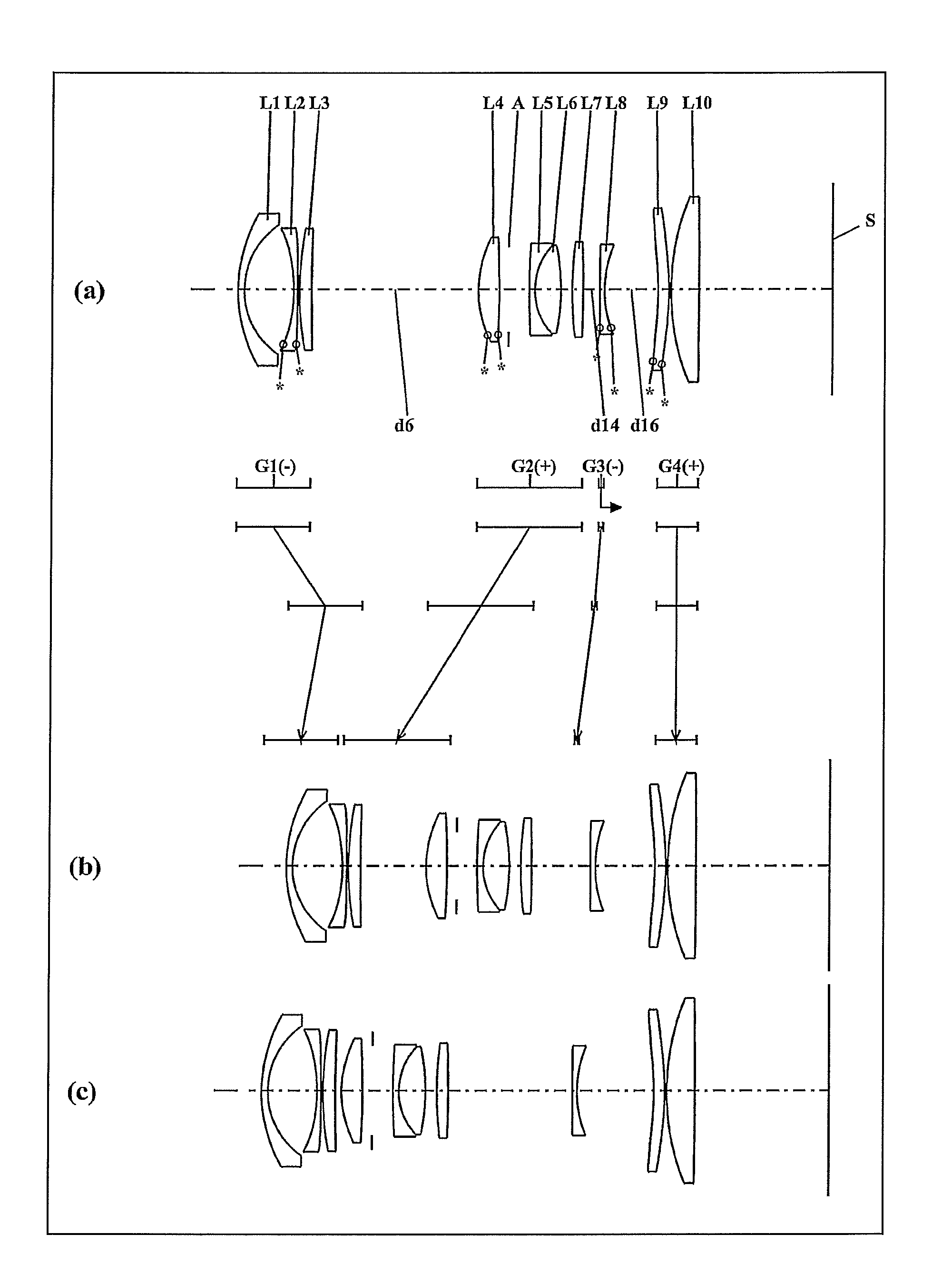
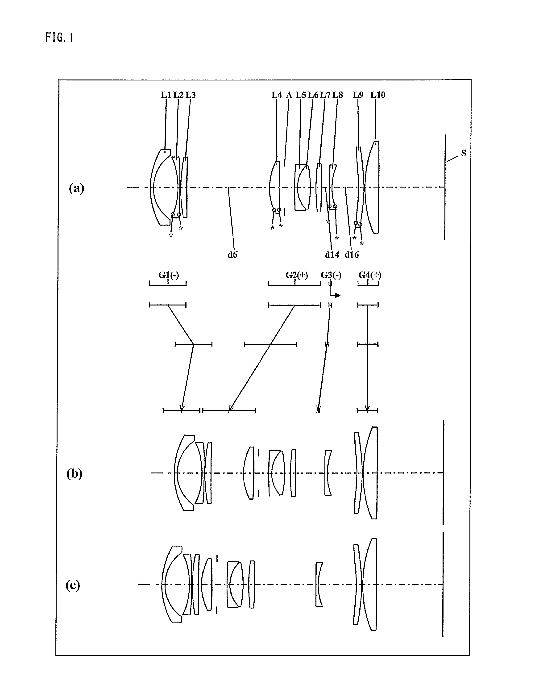
[0149]The zoom lens system of Numerical Example 1 corresponds to Embodiment 1 shown in FIG. 1. Table 1 shows the surface data of the zoom lens system of Numerical Example 1. Table 2 shows the aspherical data. Table 3 shows various data in an infinity in-focus condition. Table 4 shows various data in a close-object in-focus condition.

[0150]

TABLE 1(Surface data)Surface numberrdndvdObject surface∞ 116.568300.650001.9108235.2 28.523105.24980 3*−16.676600.400001.5825059.4 4*−1000.000000.20000 534.396001.299301.9459518.0 6260.71640Variable 7*11.946102.237801.7720050.0 8*−77.577401.00000 9(Diaphragm)∞2.181601080.104000.639501.8061033.3117.034402.787401.4970081.612−22.520801.200001338.917501.208201.5317248.814−129.76850Variable15*−2520.031700.500001.8540040.416*13.36070Variable17*−35.513401.191201.5400056.018*−32.315900.200001927.439602.895301.7495035.020−1000.00000(BF)Image surface∞

[0151]

TABLE 2(Aspherical data)Surface No. 3K = 0.00000E+00, A4 = 1.14330E−04, A6 = −2.73642E−06,A8 = −1.81751...

numerical example 2

[0154]The zoom lens system of Numerical Example 2 corresponds to Embodiment 2 shown in FIG. 5. Table 5 shows the surface data of the zoom lens system of Numerical Example 2. Table 6 shows the aspherical data. Table 7 shows various data in an infinity in-focus condition. Table 8 shows various data in a close-object in-focus condition.

[0155]

TABLE 5(Surface data)Surface numberrdndvdObject surface∞ 1*15.944000.800001.8540040.4 2*9.186605.45700 3*−16.565600.600001.5870059.6 4*77.773200.20000 518.206601.187602.0027219.3 627.70810Variable 7*11.632301.872601.7555045.6 8*109.137301.11080 9(Diaphragm)∞2.000001020.743800.400001.9036631.3117.492602.917601.4970081.612−28.986600.500001329.362601.300001.5673242.814−117.07410Variable15*39.867400.400001.8100041.016*9.10200Variable17*62.272203.589701.7555045.618*−36.34380(BF)Image surface∞

[0156]

TABLE 6(Aspherical data)Surface No. 1K = 0.00000E+00, A4 = 0.00000E+00, A6 = 6.26882E−07,A8 = 0.00000E+00 A10 = 0.00000E+00Surface No. 2K = 0.00000E+00, A4 = ...

numerical example 3

[0159]The zoom lens system of Numerical Example 3 corresponds to Embodiment 3 shown in FIG. 9. Table 9 shows the surface data of the zoom lens system of Numerical Example 3. Table 10 shows the aspherical data. Table 11 shows various data in an infinity in-focus condition. Table 12 shows various data in a close-object in-focus condition.

[0160]

TABLE 9(Surface data)Surface numberrdndvdObject surface∞ 116.292300.800001.8540040.4 2*8.676005.40160 3*−16.207200.500001.5870059.6 4*−1000.000000.20000 522.194601.195501.9459518.0 641.05000Variable 7*11.897902.016401.7720050.0 8*−1000.000001.00000 9(Diaphragm)∞2.000501025.414900.609701.9036631.3117.343102.724501.4970081.612−32.769401.500001335.205701.200001.5814440.914−84.81640Variable15*88.407500.400001.7720050.016*10.68150Variable17*43.366603.182101.7720050.018*−62.76820(BF)Image surface∞

[0161]

TABLE 10(Aspherical data)Surface No. 2K = 0.00000E+00, A4 = −3.06801E−05, A6 = −4.39134E−07,A8 = 0.00000E+00 A10 = 0.00000E+00Surface No. 3K = 0.00000E...


PUM


Abstract

A zoom lens system, in order from an object side to an image side, comprising a first lens unit having negative optical power, a second lens unit having positive optical power, a third lens unit having negative optical power, and a fourth lens unit having positive optical power, wherein the first lens unit is composed of at least three lens elements, has at least one lens element having positive optical power, and moves along an optical axis in zooming, and the conditions: np>1.88 and 1.5<fp / fW<4.0 (np and fp: a refractive index to the d-line and a focal length of a lens element having the highest refractive index among the lens elements having positive optical power in the first lens unit, fW: a focal length of the entire system at a wide-angle limit) are satisfied; an interchangeable lens apparatus; and a camera system are provided.

Description

CROSS-REFERENCE TO RELATED APPLICATION[0001]This application is based on application No. 2010-286698 filed in Japan on Dec. 22, 2010, the contents of which are hereby incorporated by reference.BACKGROUND OF THE INVENTION[0002]1. Field of the Invention[0003]The present invention relates to zoom lens systems, interchangeable lens apparatuses, and camera systems. In particular, the present invention relates to: compact and lightweight zoom lens systems having short overall length, and excellent optical performance with sufficiently compensated aberrations; and interchangeable lens apparatuses, and camera systems, each employing the zoom lens system.[0004]2. Description of the Background Art[0005]In recent years, interchangeable-lens type digital camera systems (also referred to simply as “camera systems”, hereinafter) have been spreading rapidly. Such interchangeable-lens type digital camera systems realize: taking of high-sensitive and high-quality images; high-speed focusing and high...

Claims


Application Information

Patent Timeline
Patent Type & Authority Patents(United States)
IPC IPC(8): G02B15/14
CPCG02B15/177G02B15/144511
Inventor IMAOKA, TAKUYA
Owner PANASONIC CORP
Why Eureka
Try Eureka