Supercharge Your Innovation With Domain-Expert AI Agents!

Programmable cylinder lock and keys for the operation thereof

a cylinder lock and cylinder technology, applied in the field of cylinder locks, can solve the problems of blocking the rotor, not being able to rotate, and not being able to take the key away from the lock and provide a change, so as to increase the effectiveness of the provision

Active Publication Date: 2014-03-04
SCHLAGE LOCK
View PDF15 Cites 0 Cited by
  • Summary
  • Abstract
  • Description
  • Claims
  • Application Information

AI Technical Summary

Benefits of technology

The main advantage of this invention is to provide a simple and sure solution to the lock problems without increasing its size, complications, and cost. It is achieved by introducing a recess in the use key, which allows it to displace in radial direction and come out of the stator groove, thus blocking the rotor and preventing it from rotating by that key. The presence of this recess increases the number of different keys that can be provided, making it more efficient. The stop bar can have multiple projections, and the use keys can have multiple recesses in front of these projections to further increase the number of keys.

Problems solved by technology

In this way, when the rotor is made to rotate by means of a use key, and the stop bar comes out of the stator groove, in the presence of the correct key said projection of the stop bar enters the corresponding recess of the key and then retains the key, whereby it is not possible to take the key away from the lock and provide a change condition.
Moreover, if in the lock is inserted a use key whose teeth are correctly codified, but that does not have in its side surface a recess corresponding to the projection of the stop bar, this latter cannot displace in radial direction for coming out of the stator groove and thus blocks the rotor, which therefore cannot be made to rotate by that key.

Method used


Image

  • Programmable cylinder lock and keys for the operation thereof
  • Programmable cylinder lock and keys for the operation thereof
  • Programmable cylinder lock and keys for the operation thereof

Examples


Embodiment Construction

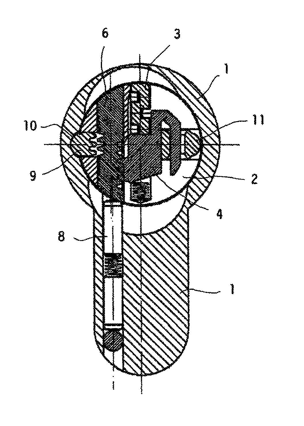
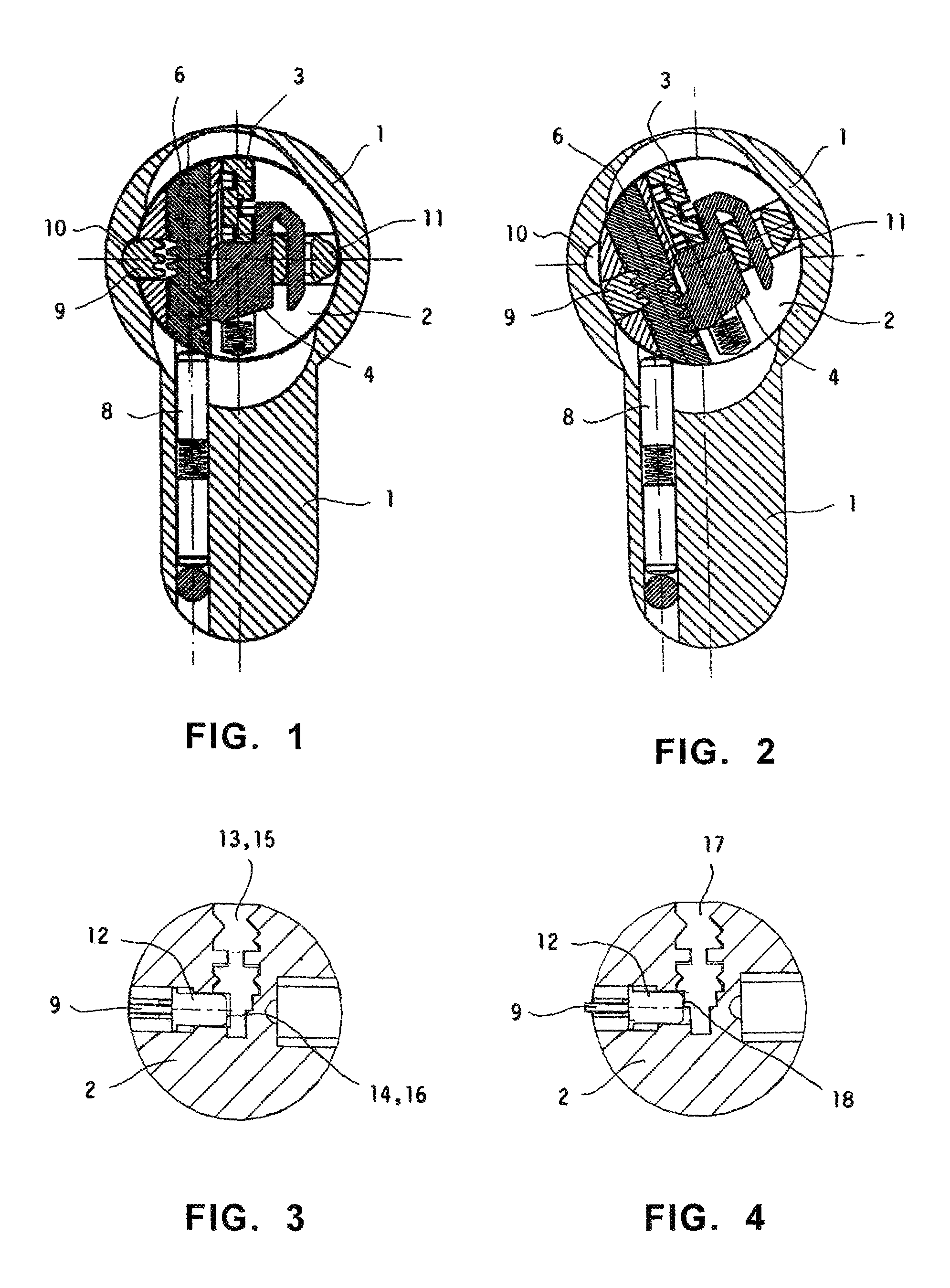
[0019]At first, reference to FIG. 1 will be made in order to recall the general structure and the operation of a lock of the considered kind, for whose particulars reference is made to the cited documents.

[0020]Number 1 designates a stator inside which there is rotatably mounted a cylindrical rotor 2 susceptible of receiving in its keyhole a key 3. In the following, it will be considered as longitudinal the direction parallel to the geometrical axis of the corresponding cylindrical rotor, and will be considered as transversal the direction perpendicular to the plane of the key and the corresponding keyhole.

[0021]In rotor 2 there are mounted key followers 4, which lies in a plane perpendicular to the axis of the cylindrical rotor 2 and are movable along the longitudinal and transversal directions. The key followers 4 are provided for cooperating with the codification conformations of key 3. Moreover, in rotor 2 there are mounted locking pins 6, and each of them is coplanar with a key...


PUM


Abstract

A programmable cylinder lock includes a stator and a cylindrical rotor mounted therein, having a keyhole and including inside the rotor key followers movable along the longitudinal and transversal directions, and locking pins movable along the longitudinal direction, the followers and locking pins forming together a number of pairs and having toothings for mutually cooperating to define the lock codification, the rotor including a stop bar cooperating with a longitudinal groove of the stator and cooperating with the locking pins, and a change bar slidingly coupled with the followers to keep them engaged with the pins and disengage them therefrom when the bar provides a lock programming position. The bar has projections facing the keyhole, and the use key has corresponding recesses to face the projections when correctly inserted in the lock, whereas the change key has a longitudinal groove extending in a position corresponding to the use key recesses.

Description

[0001]The subject of this invention is a programmable cylinder lock, namely a lock comprising devices intended to allow the initial codification of the lock or, through a change operation, to modify the former lock codification in order to adjust the lock for being operated by a key different from the key to which the lock was formerly adapted.[0002]More particularly, the invention concerns improvements in a kind of programmable cylinder lock which is known from the European Patents Nos. 0.226.252 and 0.900.310.BACKGROUND OF THE INVENTION[0003]The programmable locks of the kind to which applies the present invention and which are described in the cited documents comprise, within a rotor rotatably mounted inside the stator, a number of key followers movable along their longitudinal and transversal directions, intended to cooperate with the codification conformations of a key inserted into the rotor keyhole, and locking pins having movability along their own longitudinal directions, w...

Claims


Application Information

Patent Timeline
IPC IPC(8): E05B29/04
CPCE05B29/0066E05B29/004Y10T70/774Y10T70/7734Y10T70/7616Y10T70/7599Y10T70/7605
Inventor LORETI, ALBERTO
Owner SCHLAGE LOCK
Features
  • R&D
  • Intellectual Property
  • Life Sciences
  • Materials
  • Tech Scout
  • Unparalleled Data Quality
  • Higher Quality Content
  • 60% Fewer Hallucinations
Learn More