
Introducer system and assembly for surgical staplers

a technology of introduction system and surgical stapler, which is applied in the field of system/assembly, can solve the problems of affecting the success of the introduction and positioning affecting the success of the surgical stapler, and affecting the surgical stapler. , to achieve the effect of facilitating the introduction and/or positioning, and facilitating the anatomical introduction of the circular stapler

Active Publication Date: 2014-03-04
TAKEI HIDEHISA THOMAS
View PDF43 Cites 1278 Cited by
  • Summary
  • Abstract
  • Description
  • Claims
  • Application Information

AI Technical Summary

Benefits of technology

This patent is about a device that helps to position a surgical stapler when performing surgery. It is designed to be attached to the stapler and helps guide it through the surgery without getting stuck. It can be easily detached from the stapler and removed using a simple pull. This device makes it easier to position the stapler and perform surgery.

Problems solved by technology

Of note, introduction and positioning of a circular stapler can be difficult in practice due to the physical structures associated with the distal end of the stapler.
Indeed, challenges exist in introducing a substantially flat surface into an orifice and thereafter advancing such flat surface through the lumen, e.g., up into the rectum, potentially encountering redundancies to the colon, redundant mucosa and / or prominent valves.
Difficulties in introducing a surgical stapler and / or positioning the surgical stapler in a desired anatomical location can inhibit its successful use.
Prior art efforts to address the above-noted issues have been less than satisfactory.

Method used


Image

  • Introducer system and assembly for surgical staplers
  • Introducer system and assembly for surgical staplers
  • Introducer system and assembly for surgical staplers

Examples


Embodiment Construction

)

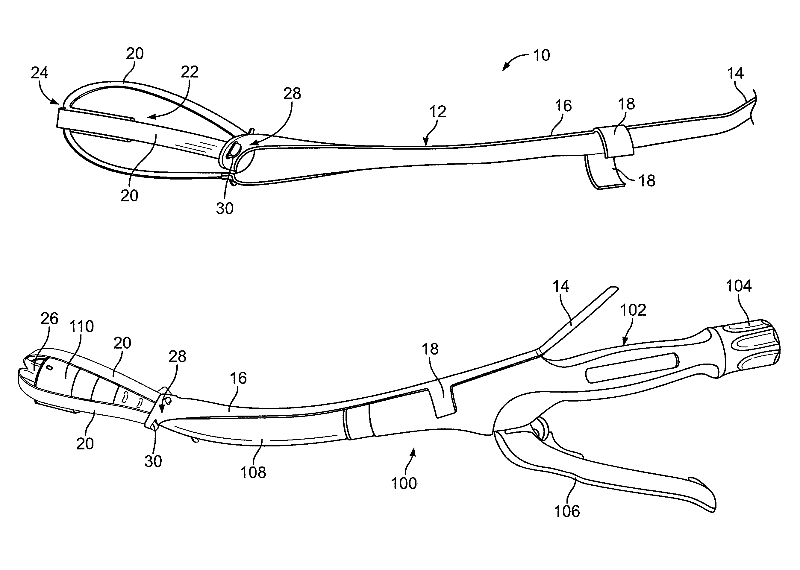
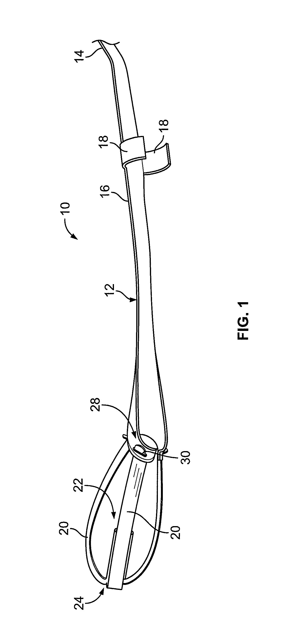
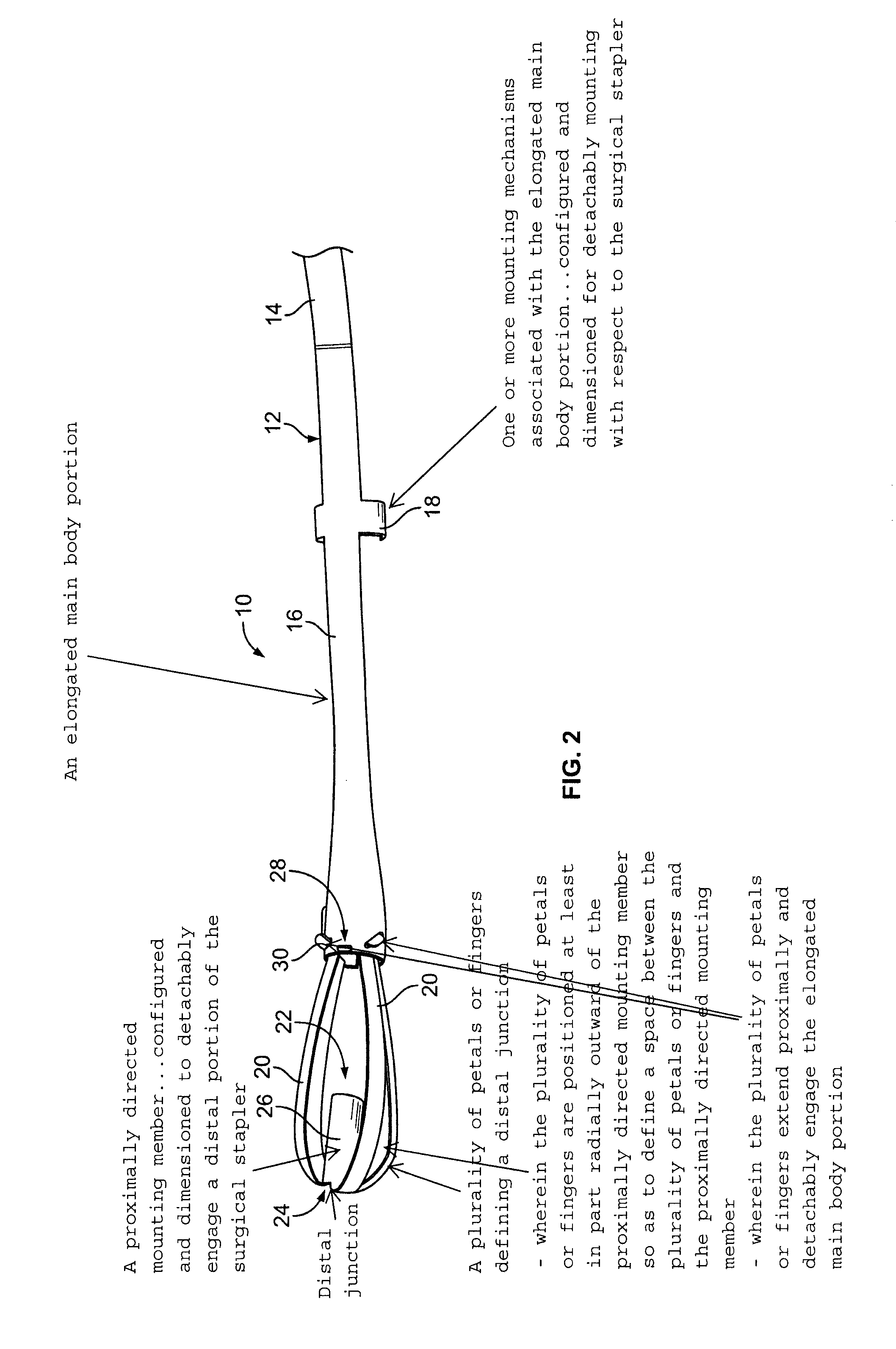
[0020]The disclosed devices, assemblies and methods advantageously facilitate introduction and / or positioning of a surgical stapler relative to a desired anatomical location. In addition, the disclosed devices, assemblies and methods permit a user to remotely detach the device / assembly from the surgical stapler, thereby permitting unobstructed operation of the surgical stapler in a desired manner. The disclosed devices, assemblies and methods also permit a user to extend the shaft of the surgical stapler, thereby permitting the surgical stapler to reach anatomical locations that otherwise may be hard to reach, while facilitating the introduction and / or positioning of the surgical stapler to these locations. The disclosed devices, assemblies and methods have wide ranging applicability and utility, including specifically applications throughout the gastrointestinal tract.

[0021]With initial reference to FIGS. 1 and 2, an exemplary introducer 10 is schematically depicted. Introducer 10...


PUM

PropertyMeasurementUnit
structureaaaaaaaaaa
forceaaaaaaaaaa
physical structuresaaaaaaaaaa

Abstract

An introducer assembly for use with a surgical stapler is provided. The introducer assembly includes an elongated main body portion, one or more mounting mechanisms associated with the main body portion, and a plurality of petals or fingers positioned at a distal end of the elongated main body portion. The one or more mounting mechanisms are adapted to detachably mount with respect to the surgical stapler. The plurality of petals or fingers define a distal junction and a proximally-directed mounting member that is adapted to detachably engage a distal portion of the surgical stapler. The plurality of petals or fingers define an inner region that accommodates a distal end of the surgical stapler. The distal junction and the proximally-directed mounting member associated with the plurality of petals or fingers are adapted to disengage upon application of a requisite proximally-directed force to the elongated body portion. Methods and combinations that utilize the introducer are also disclosed.

Description

BACKGROUND[0001]1. Technical Field[0002]The present disclosure is directed to a system / assembly for facilitating introduction and / or positioning of a surgical stapler at or to a desired anatomical location. More particularly, the present disclosure is directed to an introducer system / assembly that is adapted to be detachably mounted with respect to a surgical stapler, e.g., an end-to-end or end-to-side anastomotic stapler.[0003]2. Background Art[0004]Wound closure techniques include the use of surgical staplers and clip appliers in many clinical applications. Surgical staplers and clip appliers take many forms and are adapted for use in various modalities. Thus, for example, certain staplers are specifically designed for application of skin staples, while others are adapted for use in internal procedures. Indeed, surgical staplers and clip appliers have been developed and are employed in both “open” and “minimally invasive” surgical procedures.[0005]One particular form of surgical s...

Claims


Application Information

Patent Timeline
Patent Type & Authority Patents(United States)
IPC IPC(8): A61B17/10A61B17/04
CPCA61B17/1155A61B2017/00623A61B17/115A61B17/1114
Inventor TAKEI, HIDEHISA, THOMAS
Owner TAKEI HIDEHISA THOMAS
Learn More