Chair base with scissor lift

Active Publication Date: 2014-03-04
DELMESTRI FABIO G
View PDF25 Cites 13 Cited by
  • Summary
  • Abstract
  • Description
  • Claims
  • Application Information

AI Technical Summary

Benefits of technology

[0006]It is still another objective of the present invention to provide a chair lift that can raise a chair by closing scissors mounted thereunder.
[0007]It is yet another objective of the present invention to provide a foot operated lift to raise or lower the seat level of a chair.
[0008]It is a further objec

Problems solved by technology

However, these previous devices are often uncomfortable to sit in for any period of time.
They also tend to be mechanically complicated and expensive to manufacture and ass

Method used


Image

  • Chair base with scissor lift
  • Chair base with scissor lift
  • Chair base with scissor lift

Examples


Example

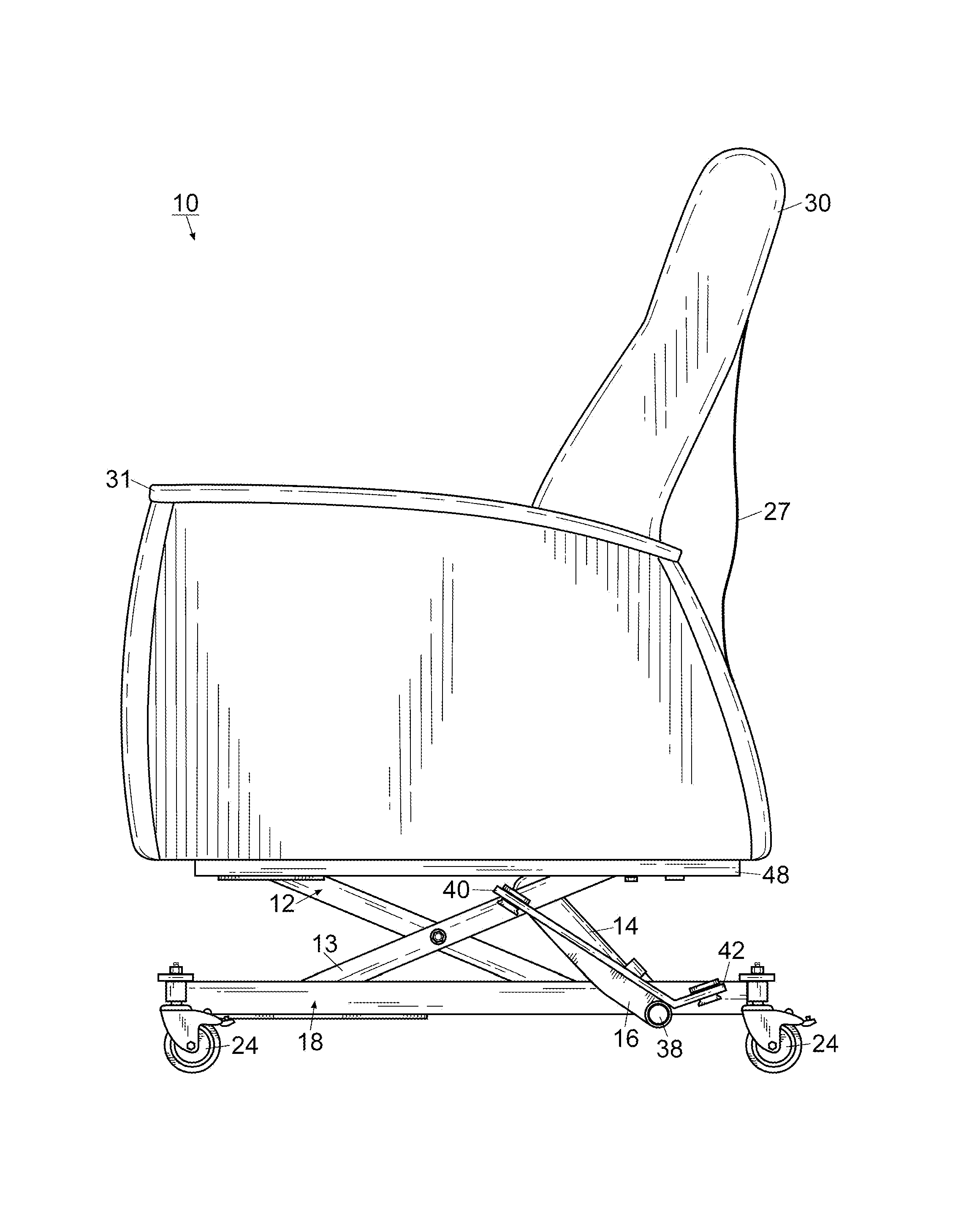
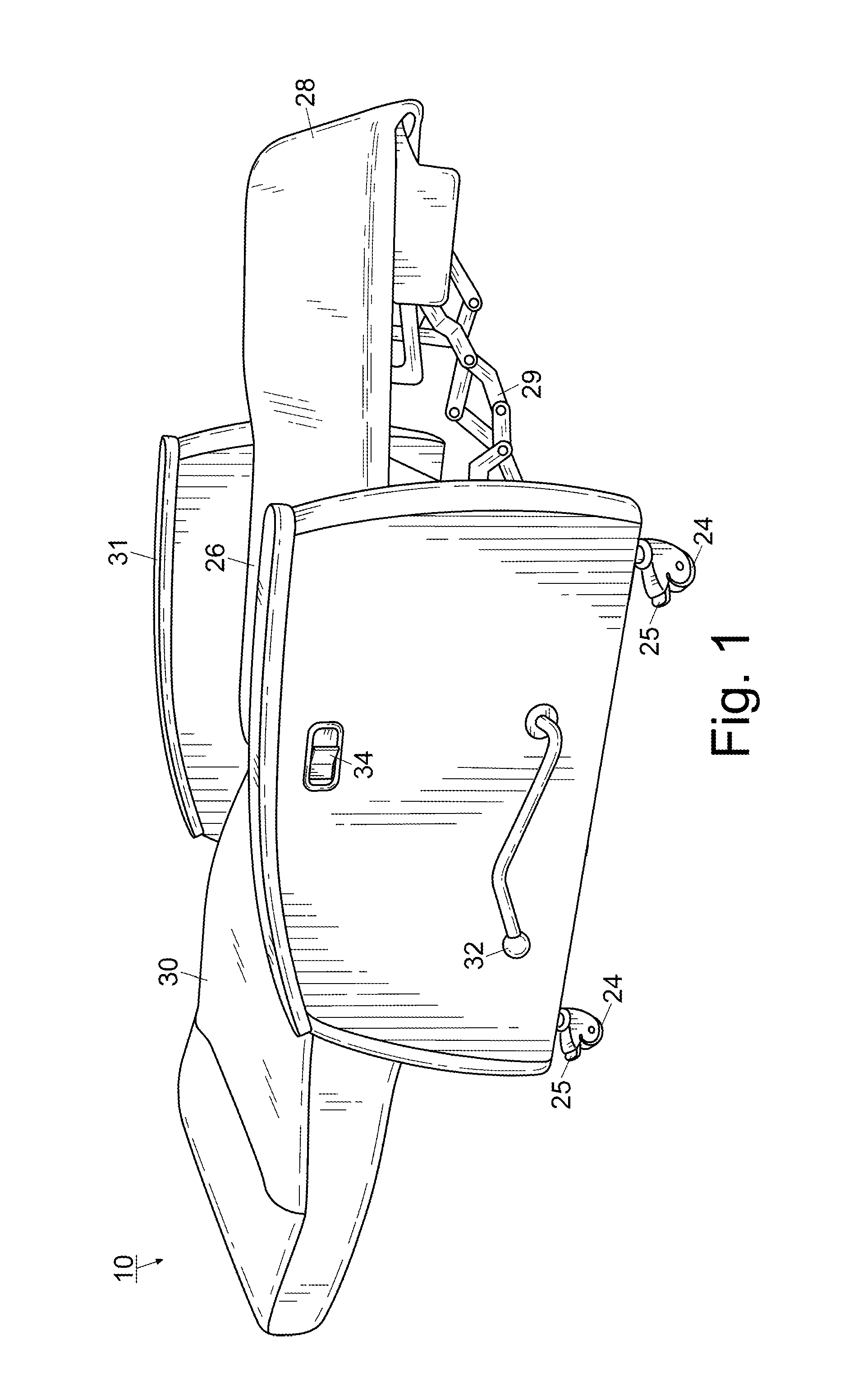
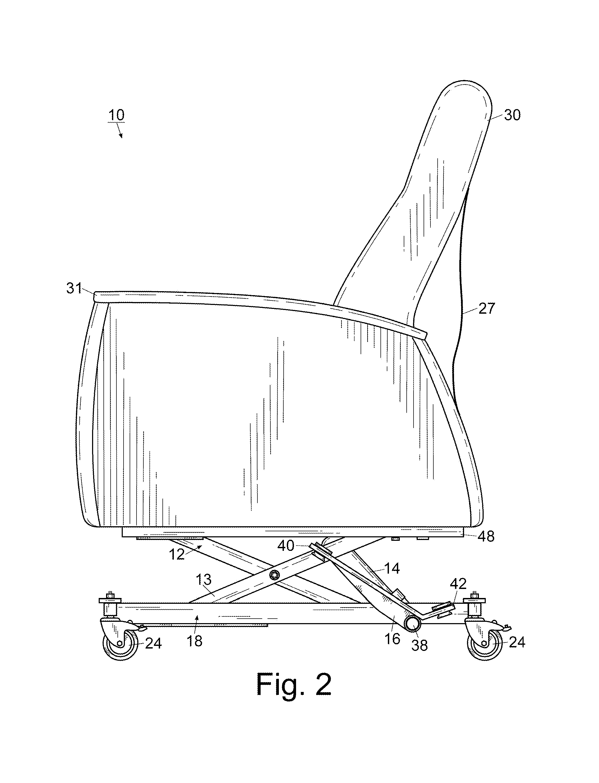
[0020]For a better understanding of the invention and its operation, turning now to the drawings, preferred metal chair lift 10 is shown in FIGS. 1-5 having scissors 12 and lifting device 14 which is affixed to chair frame 48 and operated by foot pedal 16. Preferred chair lift 10 is formed from rigid steel to provide for support of different weights and stability during repeated use though aluminum or other materials as suitable may also be used. Chair lift 10 can be used with any of a variety of furniture seats and backs (not shown) integrally formed or molded depending on the desired look and use required. Preferred chair lift 10 includes rectangular carriage 18 that supports and carries lifting device 14. Carriage 18 is preferably comprised of flat, planar members 20, 20′ that form the shorter lengths of the rectangle, and tubular members 22, 22′ that make up the longer sides as shown in FIG. 4. Carriage 18 also preferably includes wheels 24 (FIG. 1) which are attached to the cor...


PUM


Abstract

A chair lift including scissors pivotally mounted to a carriage and a lifting device pivotally positioned within the carriage. The lifting device closes the scissors and lifts the chair as desired.

Description

FIELD OF THE INVENTION[0001]The invention herein pertains to a chair base and particularly pertains to a chair having an extendable scissor lift which extends vertically as needed.DESCRIPTION OF THE PRIOR ART AND OBJECTIVES OF THE INVENTION[0002]Various types of furniture having lifts of some type are well known in the art. Specifically in the medical industry, it is often desirable for a patient to recline in a single piece of furniture that is comfortable while waiting for medical attention as well as functional during examination or treatment. Many of these devices have retractable leg and foot supports, such as shown in co-pending U.S. application Ser. No. 13 / 426,813. Others have reclining seat backs, such as shown in U.S. Design Pat. No. 432,804. Still others have lifting mechanisms, such as shown in U.S. Pat. No. 6,382,725.[0003]However, these previous devices are often uncomfortable to sit in for any period of time. They also tend to be mechanically complicated and expensive ...

Claims


Application Information

Patent Timeline
IPC IPC(8): A47C1/00
CPCA61G2200/16A61G5/1059A47C1/00A61G7/16A61G13/0018A61G2005/1081A61G5/1081
Inventor DELMESTRI, FABIO, G.
Owner DELMESTRI FABIO G
Why Eureka
Try Eureka