Self-filling modular barrier

a modular barrier and self-filling technology, applied in mechanical devices, gravity dams, rod connections, etc., can solve the problems of affecting the stability of the structure, the risk of direct flooding in 1.5% of the country, and the inability to inflict damage to assets worth over £200 billion, so as to minimize storage space and facilitate assembly for users

Active Publication Date: 2014-03-04
BU INNOVATIONS LTD
View PDF23 Cites 17 Cited by
  • Summary
  • Abstract
  • Description
  • Claims
  • Application Information

AI Technical Summary

Benefits of technology

[0021]The present invention provides a modular flood barrier that can protect households or premises from flood damage. It is simple and easy for users to assemble and can be used in a number of scenarios. No in situ preparation is required, the barrier being formed as units connected by slide-in keys to create a flexible watertight barrier. In an embodiment, the units have been designed to nest together, one upside down on the other, to minimize storage space when not in use.

Problems solved by technology

It is estimated that flooding has the potential to inflict damage to assets of over £200 billion.
These locations are susceptible to frequent flooding.
In addition, 1.5% of the country is at risk from direct flooding from the sea.
In many instances they are not willing to insure a property at all, if located on a flood plain and at risk from regular flooding.
However thy have number of disadvantages, which include the following:Time-consuming to assemble into barriers.Prone to leakage.Viral and bacterial infections are often present in flood water and can in turn be transferred onto used sandbags.Large amount of material required to form a defensive wall.Large amount of manpower required to assemble a barrier in sufficient time.
The lengthy time needed to assemble a sandbag barrier and the manpower requirements significantly reduce the chances of a defence being erecting in time to protect against rising flood waters.
It has been produced in a free-standing version which does not require in situ preparation, but a substantial time is needed for establishing a watertight seal and in use the resulting barrier requires a large number of sandbags.
However, the barrier requires in situ preparation in the form of bolts in the ground, and requires a considerable workforce to move the units into place.

Method used


Image

  • Self-filling modular barrier
  • Self-filling modular barrier
  • Self-filling modular barrier

Examples


Embodiment Construction

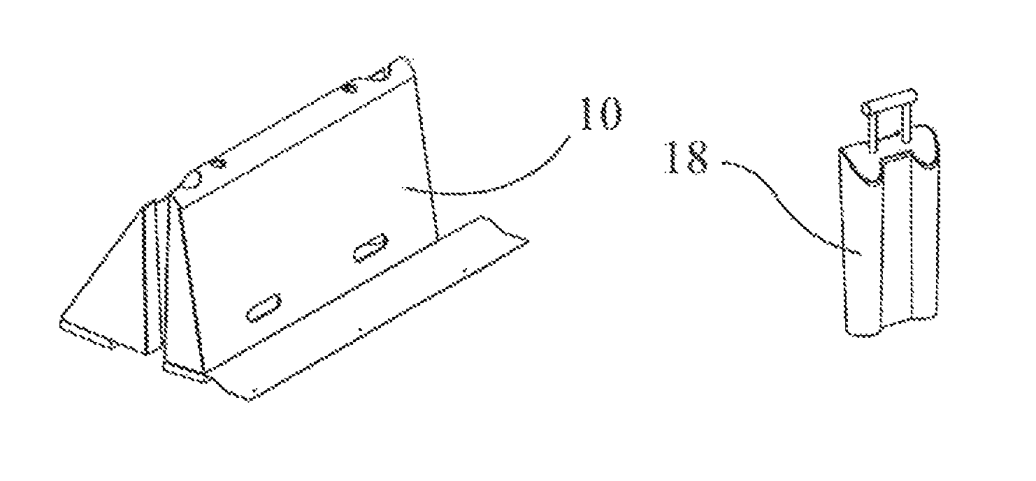
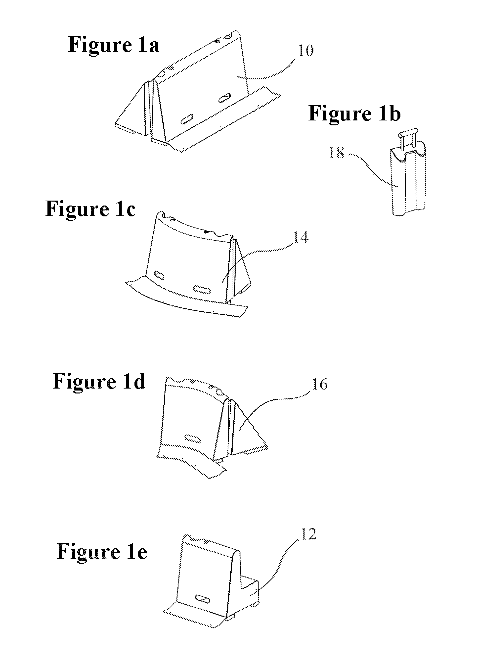
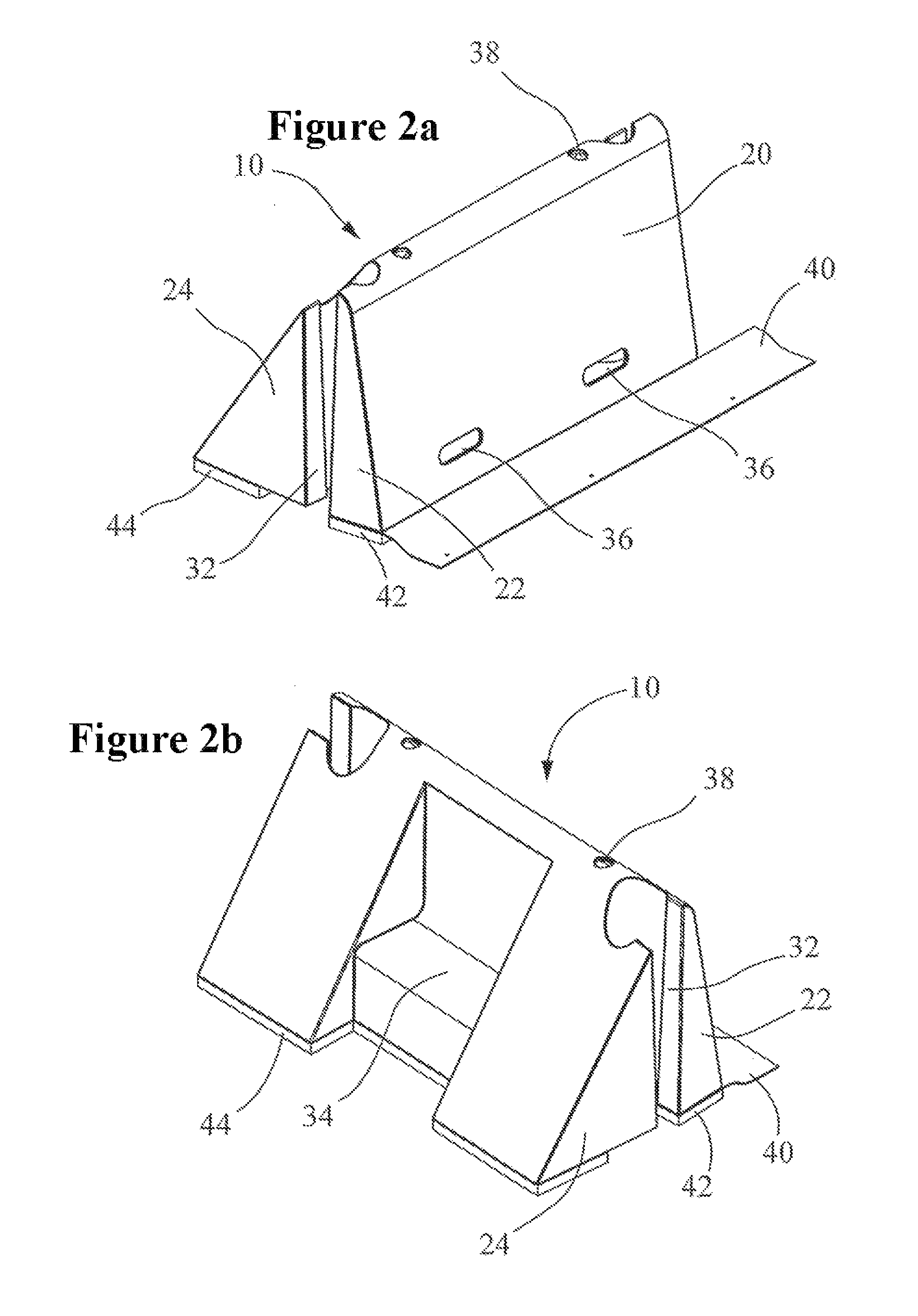
[0035]FIG. 1 is a general view of the major components that may be used to form a flood barrier according to the invention. These include a straight modular unit 10 shown in front and rear oblique views, a shorter or “spanning” modular unit 12, an inwardly-facing curved modular unit, an outwardly-facing curved modular unit 16 and a tapered universal key 18 for connecting adjacent units together. The units may be assembled together end-to-end to create a barrier to water ingress e.g. as a flood defense, for water containment e.g. to create a pool or pond and as a linear barrier e.g. to span a gap in a wall, in the latter case a small number of sandbags being used to provide a water-tight connection at either end of the barrier.

[0036]In one embodiment, which will be described in detail below, the barrier has a height of 500 mm, but it will be appreciated that other dimensions are possible, e.g. an overall height of 1 meter.

[0037]The modular units used in the present flood barrier may ...


PUM


Abstract

A flood barrier comprises hollow self-filling units (10, 12, 14, 16) placed end-to-end and connected at their ends by downwardly tapered bilobal (46) keys inserted into sockets (26, 28) at the ends of the units, wherein the keys incorporate concrete or other ballast for negative buoyancy.

Description

FIELD OF THE INVENTION[0001]The present invention provides modular barrier apparatus for protecting households or premises from flood damage or to provide a barrier for the containment of fluids. The barrier is simple, easy and rapid for users to assemble and it can be used in a number of scenarios without the need for in-situ preparation. It is based on modular units for assembly in end-to-end abutting relationship and connectable using slide-in keys to create a flexible watertight barrier.BACKGROUND TO THE INVENTION[0002]Globally flooding is becoming more and more frequent due to climate change and the increase in development on floodplain. Nearly 2 million properties are situated in flood risk areas within the UK. It is estimated that flooding has the potential to inflict damage to assets of over £200 billion. Some evidence of this can be seen in 2000, when insurance claims regarding flood damage were as high as £800 million.[0003]Over 5% of people in England live lower then 5 me...

Claims


Application Information

Patent Timeline
Patent Type & Authority Patents(United States)
IPC IPC(8): F16B13/00E02B3/10E02B7/10
CPCE02B3/108Y10T403/559E02B3/10E02B7/20
Inventor PHELPS, SIMON, THOMAS
Owner BU INNOVATIONS LTD
Why Eureka
Try Eureka