Stretch-blow molding machine

a technology of stretch blowing and molding machine, which is applied in the direction of dough shaping, manufacturing tools, food shaping, etc., can solve the problems of time-consuming reset work and complicated handling of this

Inactive Publication Date: 2014-03-04
KRONES AG
View PDF16 Cites 0 Cited by
  • Summary
  • Abstract
  • Description
  • Claims
  • Application Information

AI Technical Summary

Benefits of technology

[0009]In one suitable embodiment, the coupling is designed such that it can be disconnected for transferring the stretching rod quick change device to the change position, and the drive unit with the electric servomotor is mounted, at least in a region adjacent to the coupling, such that it can be displaced from the path of movement of the stretching rod in the direction of change. During the transfer of the stretching rod quick change device to the change position, not only the stretching rod is released to be changed by disconnecting the coupling, but the drive unit with the servomotor is moreover displaced out of the path of movement of the stretching rod so that the stretching rod can be comfortably changed. The functional combination of the disconnectable coupling and the displaceable drive unit thus eliminates in a structurally simple way the impairment caused by the drive unit with the electric servomotor which is inherent in a blow molding station designed for electric stretching.
[0024]In one suitable embodiment, the servomotor is in the operating position additionally positively locked at the bearing support in the moving direction parallel to the stretching rod. This locking prevents relative movements of the servomotor at the bearing support even under maximum forces.

Problems solved by technology

Time-consuming reset works are required for changing a stretching rod.
The handling of this is complicated.

Method used


Image

  • Stretch-blow molding machine
  • Stretch-blow molding machine
  • Stretch-blow molding machine

Examples


Embodiment Construction

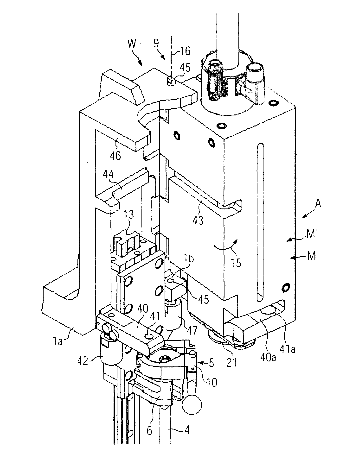
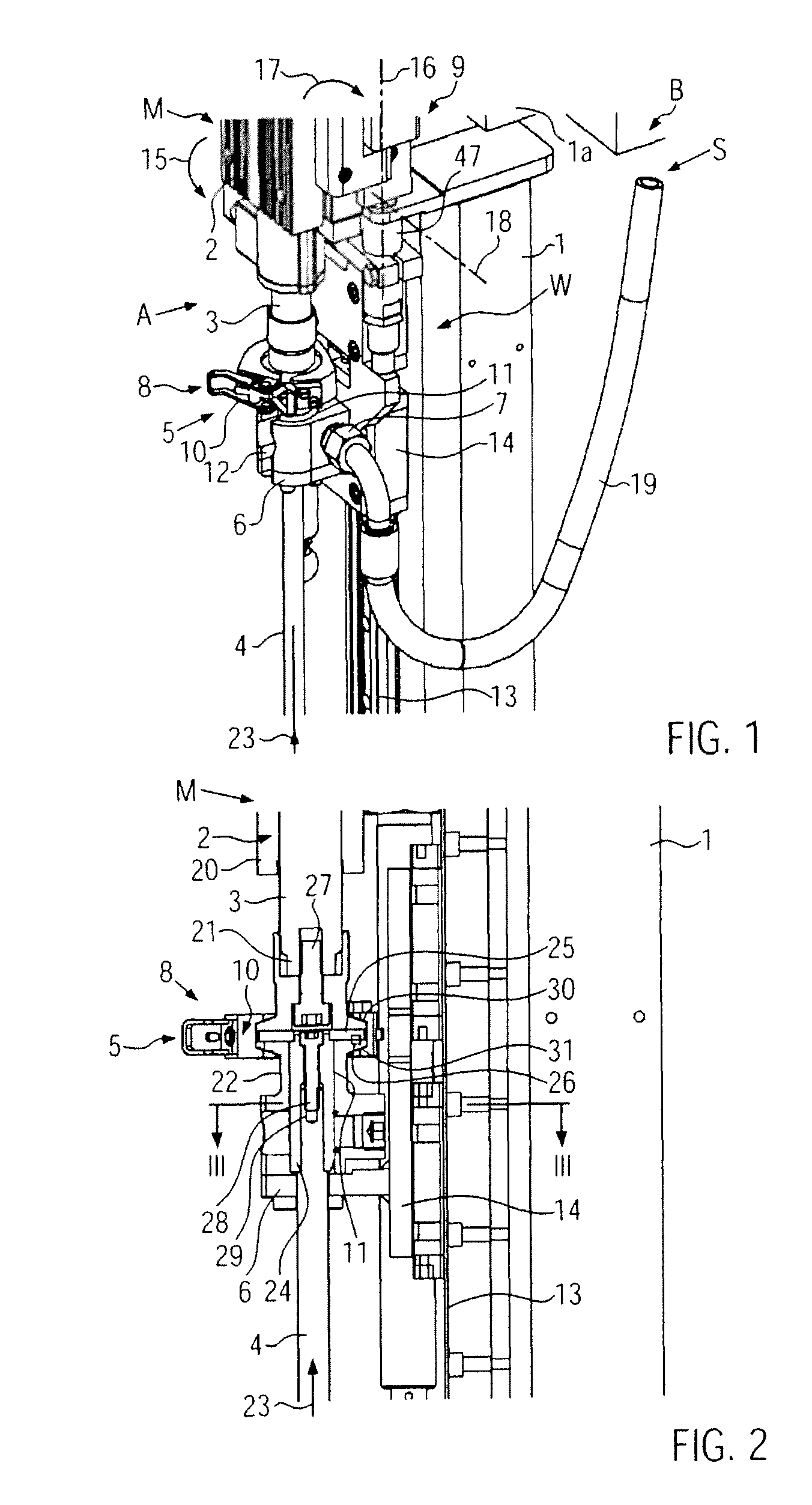
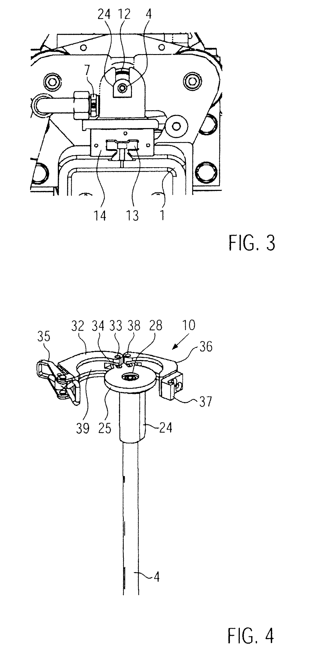
[0033]In FIGS. 1-6, a portion of a blow molding station S of a stretch-blow molding machine B is illustrated in which a stretching rod quick change device W is provided which on the one hand provides a stable, centered backlash-free and quickly releasable connection between a drive unit A with a servomotor M and a stretching rod 4 which can electrically stretch preforms in a non-depicted blow mold, and which on the other hand permits at any time a comfortable and quick change of the stretching rod without having to dismount components of the blow molding station S, despite the spatial restriction given due to the stretching slide 6 and the drive unit when the stretching rod 4 is changed in a given direction of change 23.

[0034]The principle according to the disclosure is not only applicable to stretch-blow molding machines where in the production operation in most cases several blow molding stations S rotate on a blow-molding unit (not shown) relative to a stationary part, but also t...


PUM

PropertyMeasurementUnit
elasticaaaaaaaaaa
outer diameteraaaaaaaaaa
displacementaaaaaaaaaa

Abstract

A stretch-blow molding machine with at least one blow molding station, where for electric stretching, at least one stretching rod is coupled with a drive unit comprising an electric servomotor, and the stretching rod can be changed in a defined, at least approximately axial direction, and has a stretching rod quick change device transferable between a centered operating position and a change position.

Description

CROSS-REFERENCE TO RELATED APPLICATION[0001]The present application claims the benefit of priority of German Patent Application No. 102010028254.5 filed Apr. 27, 2010. The entire text of the priority application is incorporated herein by reference in its entirety.FIELD OF THE DISCLOSURE[0002]The disclosure relates to a stretch-blow molding.BACKGROUND[0003]In a stretch-blow molding machine known from DE 10325229 A, an electric linear drive is provided for positioning the stretching rod in electric stretching. To be able to change the stretching rod, the electric linear drive must be dismounted.[0004]In the stretch-blow molding machine known from WO 2006 / 108380 A, the stretching rod is positioned by an electric linear motor and additionally by a fluid drive. The stretching rod is retained in a stretching slide. A releasable coupling is provided between the stretching rod and either an extension element or a rotor of the linear motor. Time-consuming reset works are required for changin...

Claims


Application Information

Patent Timeline
Patent Type & Authority Patents(United States)
IPC IPC(8): B29C49/00
CPCB29C49/42B29C2049/1204B29C49/12B29C2049/129B29C49/06B29C49/1202B29C49/123B29C2949/0715
Inventor WEISS, JOHANNES
Owner KRONES AG
Why Eureka
Try Eureka