Negative pressure wound therapy device

a wound therapy and negative pressure technology, applied in the field of negative pressure wound therapy devices, can solve the problems of increasing the time needed to deploy a conventional negative pressure wound therapy device, reducing the effectiveness of treatment, so as to improve the ability to use, prevent exudates, and improve the effect of treatment

Active Publication Date: 2014-03-04
SMITH & NEPHEW INC
View PDF439 Cites 122 Cited by
  • Summary
  • Abstract
  • Description
  • Claims
  • Application Information

AI Technical Summary

Benefits of technology

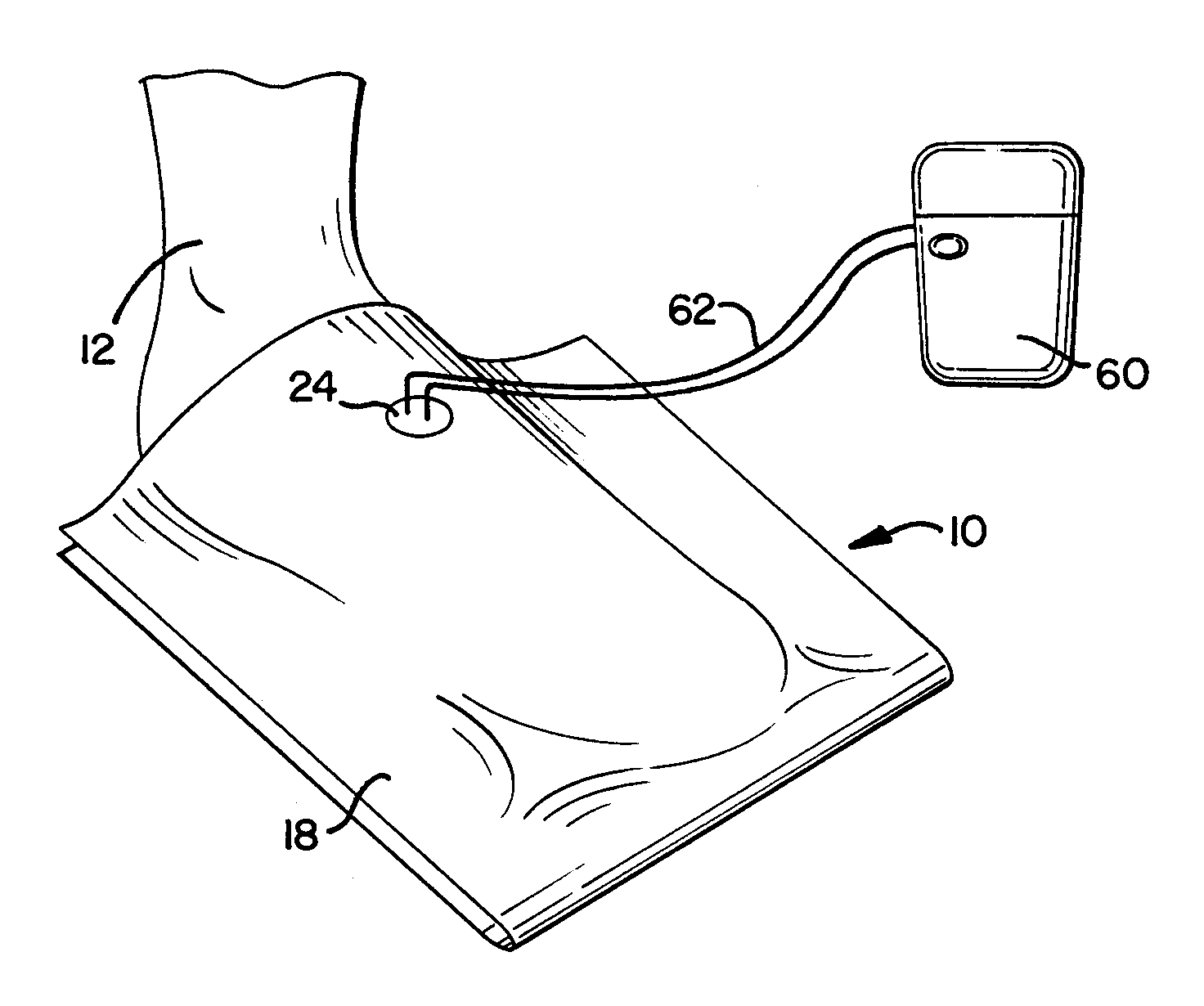
[0009]The port may be configured to prevent exudates from flowing through the port towards the pump (which supplies the negative pressure).
[0027]The method may further include preventing exudates from flowing through the port.
[0028]A device and method as described herein is believed to provide a variety of benefits to aid in the treatment of a wound with negative pressure wound therapy.
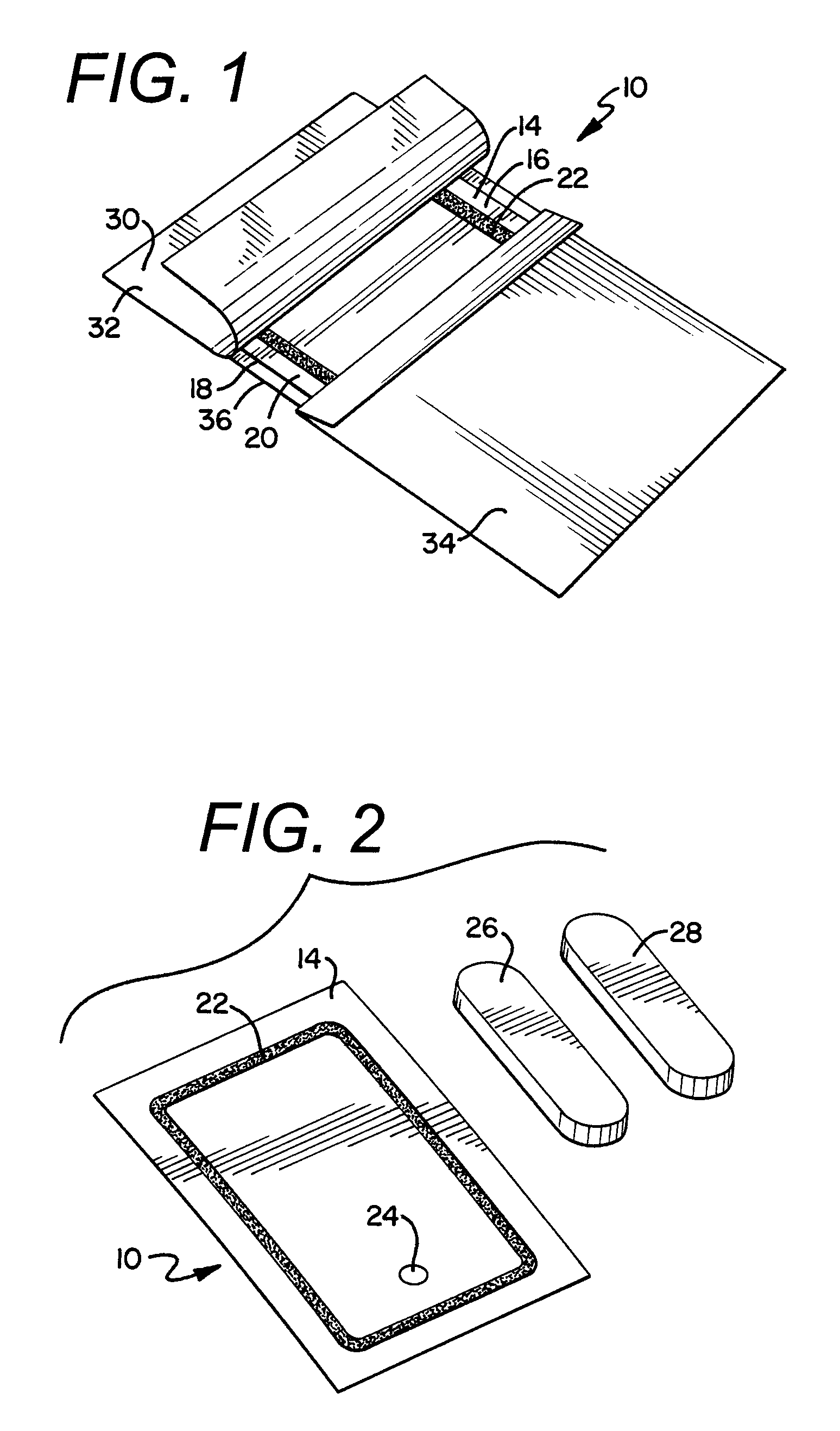
[0029]First, such a device and method would provide for a device to be applied with a multitude of configurations when compared with conventional devices that come completely pre-arranged. In other words, a medical professional is able to determine the best location for the wound interface layer and non-woven absorption material and position those portions of the devices separate and apart from the housing material with the port. This will increase the ability to utilize such a device and method on wounds that, because of the location of the wound, are difficult to effectively treat with negative pressure wound therapy.
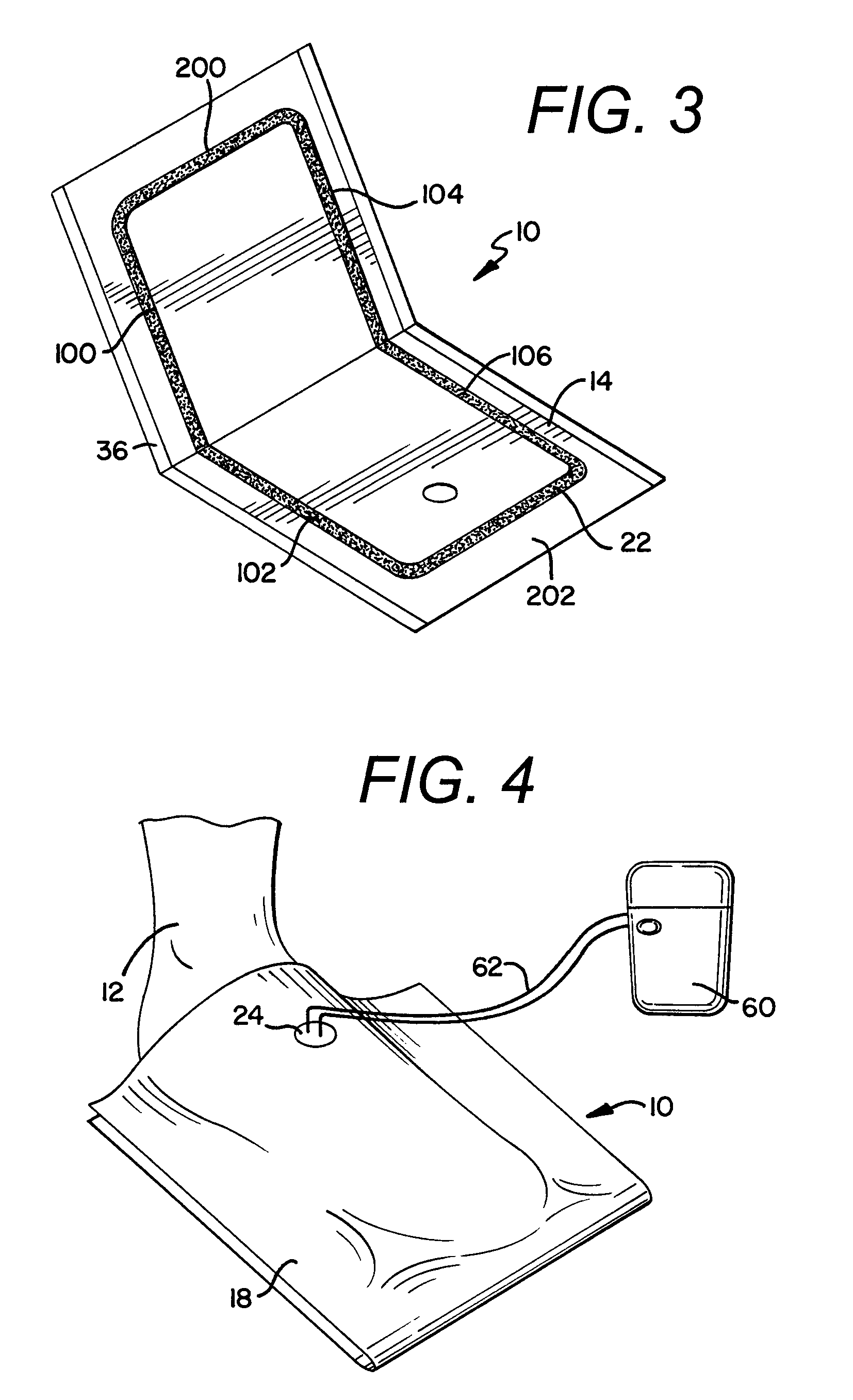
[0030]In addition, the design is believed to provide an improved seal compared with some of the negative pressure wound therapy devices that are currently commercially available. The improved seal results in less time needed to confirm that the device has obtained overall satisfactory seal and less time adjusting the device to eliminate gaps and other spaces that allow negative pressure to dissipate and result in the device performing with a reduced efficiency.

Problems solved by technology

Conventional negative pressure therapy devices are generally large in size and often require the use of complicated equipment such as suction pumps, vacuum pumps and complex electronic controllers.
With respect to a wound located on a foot, there are specific drawbacks involving the time needed to deploy a conventional negative pressure wound therapy device.
In addition, due to the shape of a foot, obtaining a satisfactory seal over the wound can be problematic and contribute to the increased time needed to deploy a conventional negative pressure wound therapy device.
Other wound locations on a patient's body may present drawbacks and problems similar to those associated with a wound on a foot.

Method used


Image

  • Negative pressure wound therapy device
  • Negative pressure wound therapy device
  • Negative pressure wound therapy device

Examples


Embodiment Construction

[0038]It will be readily understood that the components of the embodiments as generally described and illustrated in the Figures herein could be arranged and designed in a wide variety of different configurations. Thus, the following more detailed description of various embodiments, as represented in the Figures, is not intended to limit the scope of the present disclosure, but is merely representative of various embodiments. While the various aspects of the embodiments are presented in drawings, the drawings are not necessarily drawn to scale unless specifically indicated.

[0039]The present invention may be embodied in other specific forms without departing from its spirit or essential characteristics. The described embodiments are to be considered in all respects only as illustrative and not restrictive. The scope of the invention is, therefore, indicated by the appended claims rather than by the foregoing description. All changes which come within the meaning and range of equivale...


PUM


Abstract

A wound therapy device and a kit for same with a housing material, a gasket disposed around at least a portion of the housing material, a non-woven absorption material, and a port. The gasket is sized and configured such that at least a first portion of the gasket will be adhered to a second portion of the gasket upon a folding of the housing material. A method of using a wound therapy device.

Description

RELATED APPLICATIONS[0001]This application claims priority to U.S. Provisional Application No. 61 / 212,947 filed on Apr. 17, 2009, the entirety of which is incorporated herein.TECHNICAL FIELD[0002]The present invention relates, in general, to a device and method for wound therapy that is capable of treating a variety of chronic and acute wound types, including, but not limited to, infection wounds, venous ulcers, arterial ulcers, diabetic ulcers, burn wounds, post amputation wounds, surgical wounds, and the like. Specifically, the present disclosure is related to wound treatment devices for a wound, for example, on a foot and methods that utilize a negative pressure therapy device for treatment of same.BACKGROUND[0003]Negative pressure therapy has been one method used for the treatment of a variety of wounds by practitioners in the art. Conventional negative pressure therapy devices are generally large in size and often require the use of complicated equipment such as suction pumps, ...

Claims


Application Information

Patent Timeline
Patent Type & Authority Patents(United States)
IPC IPC(8): A61M27/00
CPCA61F13/02A61M1/0088A61M2210/086A61F17/00A61F13/064A61F13/0206A61F13/0259A61F13/0216A61F13/00068A61M1/917A61M1/916A61M1/985A61F13/0253A61F13/51456
Inventor BUAN, JOHNCARLSON, ALANGELFMAN, DANIEL
Owner SMITH & NEPHEW INC
Why Eureka
Try Eureka