
Musical instrument pickup and methods

Active Publication Date: 2014-03-04
LAWING ANDREW SCOTT
View PDF141 Cites 6 Cited by
  • Summary
  • Abstract
  • Description
  • Claims
  • Application Information

AI Technical Summary

Benefits of technology

The present invention provides a musical instrument pickup design platform that maintains symmetry between the coil geometry and the associated magnetic field. This design helps to improve the overall performance of the pickup and minimize interference between strings. The pole piece cap is optionally associated with the coil wire wrapping and helps to extend the magnetic flux to the coil. The coil geometry is arranged such that each coil is associated with a single string and maximizes the overlap between strings. This configuration also alleviates non-idealities associated with reduced signal strength and coupling of string vibration.

Problems solved by technology

A significant and persistent drawback to traditional single coil pickups is noise.
Due to their lack of active or effective passive noise reduction, single coil pickups are plagued by the fact that they tend to produce large amounts of background noise due to their tendency to pickup and transmit ambient electromagnetic signals, especially at higher gain amplification settings.
While some of these approaches have enjoyed commercial success, there is still a feeling among many guitarists that they do not quite match the tonal characteristics of a traditional single coil pickup.
For example, the stacked designs where the lower coil is typically a “noise sensing” coil are perceived to be tonally inferior to standard single coil designs, presumably due to the tone affecting properties of the subservient lower coil.
P90 pickups are also prone to noise issues.
Very little work has been done to quantify basic pickup electrical response and tie it to tonal performance.
The effect of material properties on pickup performance, while recognized as important, has been very poorly and incompletely understood.
Their work, however, falls far short of the sophistication necessary to accurately capture the essence of the surprisingly complex nature of guitar pickups.

Method used


Image

  • Musical instrument pickup and methods
  • Musical instrument pickup and methods
  • Musical instrument pickup and methods

Examples


Embodiment Construction

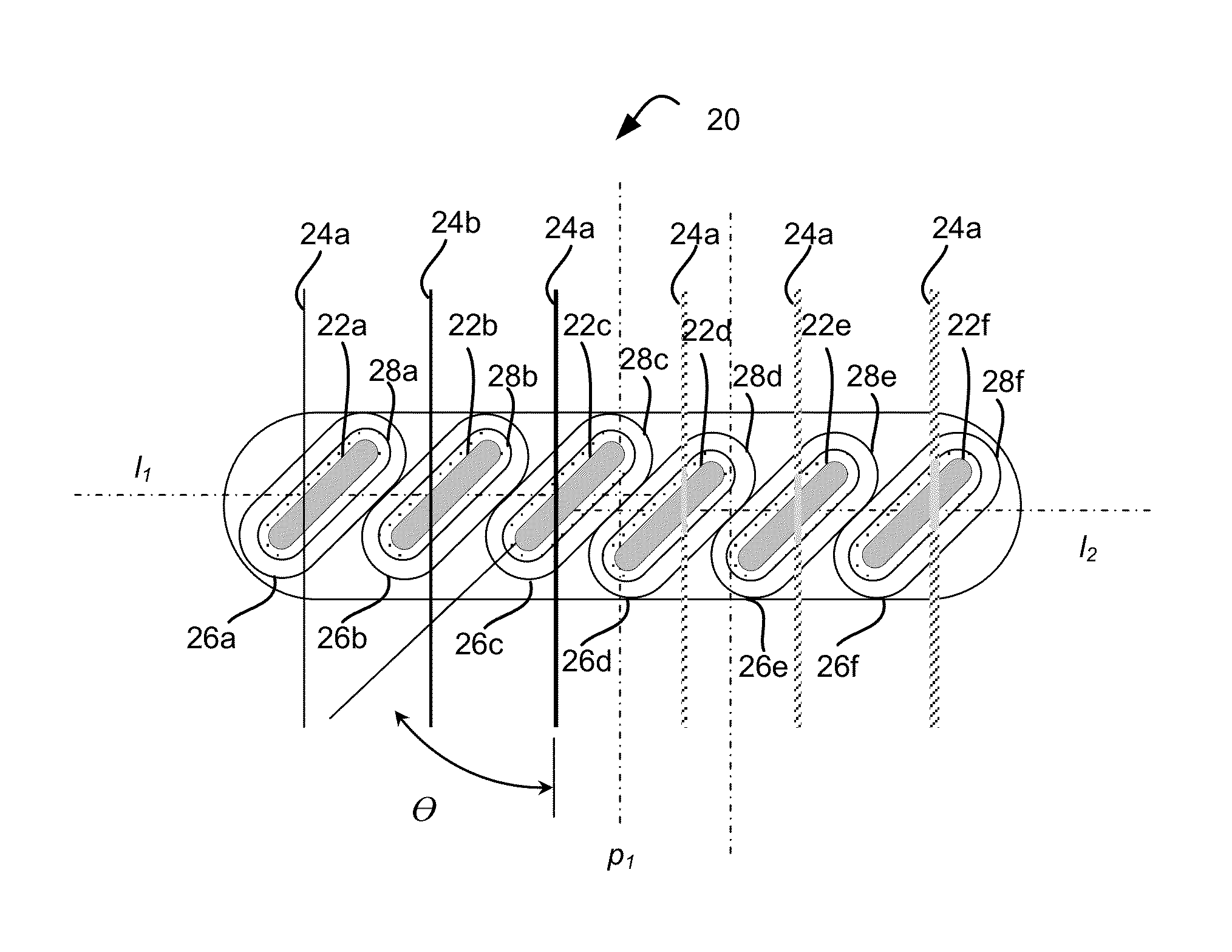
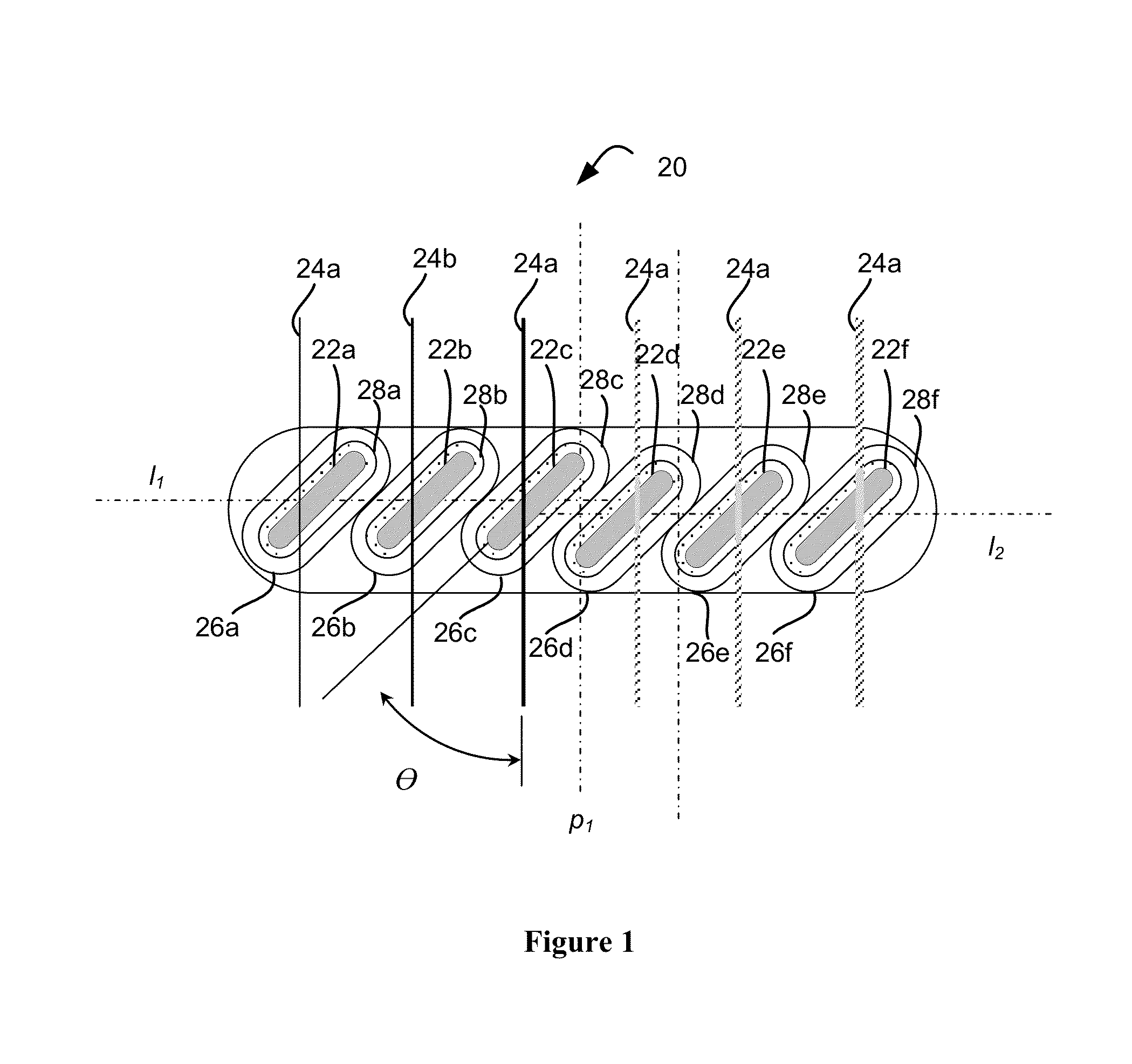
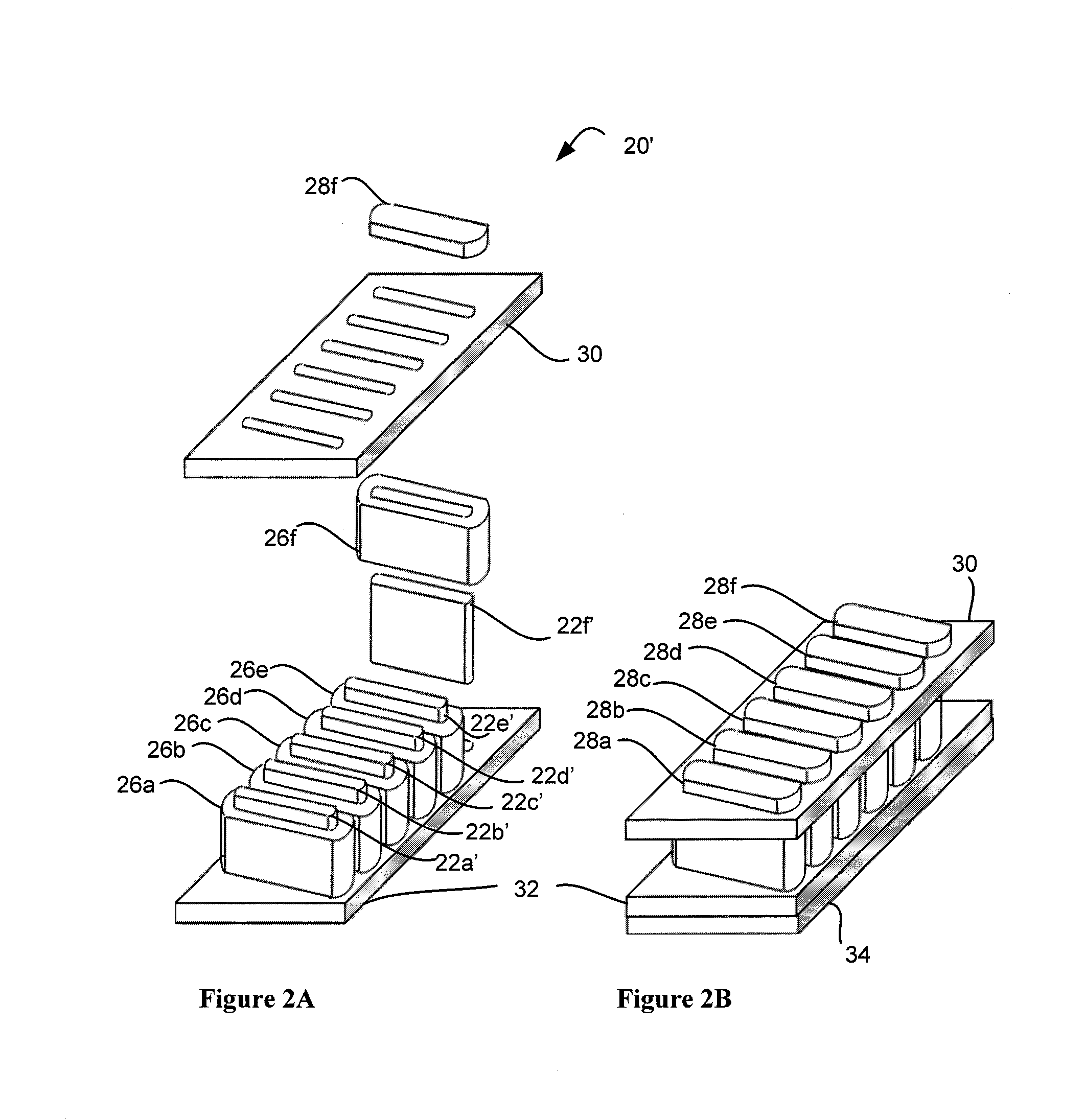
[0046]A first embodiment of an inventive pickup 20 is illustrated in FIG. 1. As shown therein, pickup 20 consists of a plurality of pole pieces 22a-22f that may be composed of generally rectangular plates characterized by a length, height and thickness (or width). As defined here, the height of the pole piece is the dimension perpendicular to the string plane and the string plane is the plane of the page surface. Further, those of ordinary skill will appreciate that the term “string plane”, as used herein, may sometimes refer to a slightly curved surface (such as the cylindrical surface), for example, where an instrument fingerboard is radiused and the strings arced accordingly. The length of each pole piece may be positioned to form a constant acute angle, illustrated in FIG. 1 as the angle θ, with respect to the axis of a corresponding string 24a-24f. Each of pole pieces 22a-22f may be formed of a permanently magnetic material, such as AlNiCo II or AlNiCo V. Alternatively, pole pi...


PUM


Abstract

Musical instrument pickups and methods of constructing same to achieve a user-desired signal output level and a user-desired tonal characteristic from a stringed instrument are disclosed. The method may include steps for selecting a coil geometry, selecting a number of coils, selecting a coil wire gauge and number of turns for each coil and selecting a pole piece. In selecting the pole piece consideration may be given to pole piece composition, pole piece thickness, height and width, and pole piece response in terms of relative inductive and relative resonant frequency characteristics and / or the shape of the frequency response in the vicinity of resonance.

Description

CROSS REFERENCE TO RELATED CASES[0001]This continuation application claims the benefit under 35 U.S.C. §120 of U.S. patent application Ser. No. 13 / 223,625 filed Sep. 1, 2011 now abandoned and entitled “Musical Instrument Pickup And Methods”, which application is hereby incorporated by reference in its entirety and which application, in turn, claimed the benefit under 35 U.S.C. 119(e) of U.S. Provisional Application Ser. No. 61 / 402,527 filed Sep. 1, 2010 and entitled “Musical Instrument Pickup and Methods”; Ser. No. 61 / 461,956 filed Jan. 26, 2011 and entitled “Musical Instrument Pickup and Methods”; and Ser. No. 61 / 525,240 filed Aug. 19, 2011 and entitled “Musical Instrument Pickup and Methods”.BACKGROUND OF THE INVENTION[0002]1. Field of the Invention[0003]This invention relates to musical instrument pickups and, more particularly, to methods of characterizing, correlating and predicting pickup performance to thereby design and construct musical instrument pickups with a predictable...

Claims


Application Information

Patent Timeline
IPC IPC(8): G10H3/00
CPCG10H3/00G10H3/143G10H3/181G10H2220/461
Inventor LAWING, ANDREW, SCOTT
Owner LAWING ANDREW SCOTT
Learn More