Supercharge Your Innovation With Domain-Expert AI Agents!

Spindle motor including a fluid dynamic bearing and disk drive apparatus with same

a technology of fluid dynamic bearing and spindle motor, which is applied in the direction of sliding contact bearings, instruments, record information storage, etc., can solve the problem of insufficient shape accuracy of the outer circumferential surface of the shaft, and achieve the effect of excellent structural rigidity and easy improvement of shape accuracy

Active Publication Date: 2014-03-11
NIDEC CORP
View PDF54 Cites 2 Cited by
  • Summary
  • Abstract
  • Description
  • Claims
  • Application Information

AI Technical Summary

Benefits of technology

This configuration improves the structural rigidity and shape accuracy of the shaft component, enabling the motor to be made thinner while maintaining structural integrity and reducing manufacturing costs, thus enhancing the motor's performance and lifespan.

Problems solved by technology

If the shaft and the first bearing component are manufactured as a single component, sufficient shape accuracy of the outer circumferential surface of the shaft may not be obtained because of the resulting complicated shape.

Method used


Image

  • Spindle motor including a fluid dynamic bearing and disk drive apparatus with same
  • Spindle motor including a fluid dynamic bearing and disk drive apparatus with same
  • Spindle motor including a fluid dynamic bearing and disk drive apparatus with same

Examples


Embodiment Construction

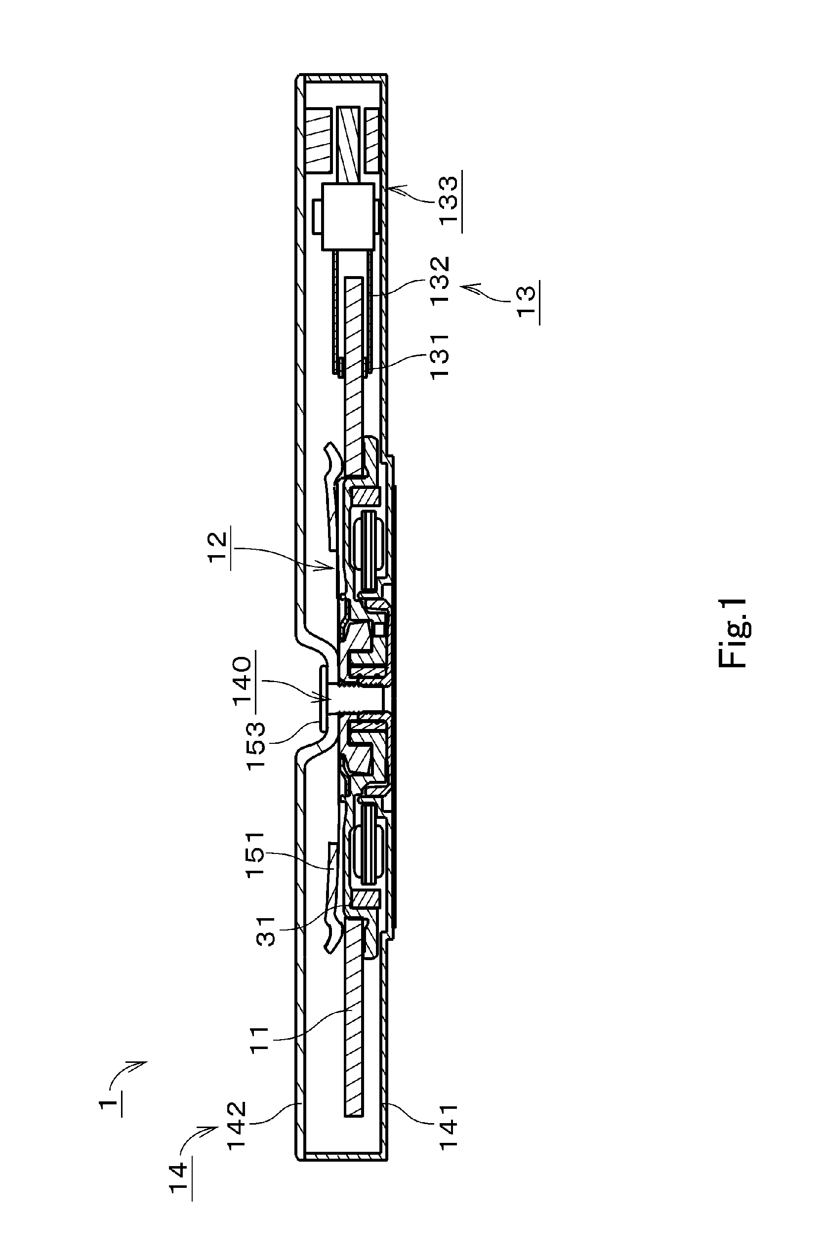
[0028]In the following description, an upper side and a lower side of FIG. 1 in a direction of a central axis of a motor are simply referred to as an “upper side” and a “lower side”, respectively. In addition, the upward and downward direction does not refer to a positional relation or a direction when being incorporated in an actual device. In addition, the direction parallel with a central axis or the direction substantially parallel therewith is referred to as an “axial direction”, the radial direction centered on the central axis is simply referred to as a “radial direction”, and the circumferential direction centered on the central axis is simply referred to as a “circumferential direction”.

[0029]FIG. 1 is a vertical cross-sectional view of a disk drive apparatus 1 including a spindle motor (hereinafter, simply referred to as a “motor”) according to an exemplary preferred embodiment of the present invention. The disk drive apparatus 1 is a so-called hard disk drive apparatus. T...


PUM

PropertyMeasurementUnit
cylindrical shapeaaaaaaaaaa
thrustaaaaaaaaaa
dynamic pressureaaaaaaaaaa

Abstract

A stationary portion of a motor includes a shaft component, an upper plate portion, and a lower plate portion. A rotating portion includes a sleeve portion which is disposed between the upper plate portion and the lower plate portion. The shaft component includes an inner shaft upper portion, an inner shaft lower portion which is located in a lower side of the inner shaft upper portion, and an outer shaft portion. The outer shaft portion is located on an outer circumferential surface of the inner shaft upper portion and an outer circumferential surface of the inner shaft lower portion. The inner shaft upper portion and the upper plate portion are preferably defined by a single monolithic member, and the inner shaft lower portion and the lower plate portion are preferably defined by a single monolithic member.

Description

BACKGROUND OF THE INVENTION[0001]1. Field of the Invention[0002]The present invention relates to an electric spindle motor and a disk drive apparatus.[0003]2. Description of the Related Art[0004]Hitherto, a bearing mechanism using a fluid dynamic pressure has been utilized in a motor of a disk drive apparatus. A spindle motor disclosed in Japanese Patent Application Publication No. 2009-136143 includes a shaft, a first bearing component, a second bearing component, and a rotor component. The first bearing component is formed in a cup shape. A lower portion of the shaft is attached in an opening of the first bearing component. The second bearing component is of an annular shape, and is formed integrally with the shaft at an upper end portion of the shaft. The rotor component is disposed within a space defined by the shaft, the first bearing component, and the second bearing component. A fluid dynamic pressure radial bearing portion is formed between a cylindrical surface of the rotor...

Claims


Application Information

Patent Timeline
Patent Type & Authority Patents(United States)
IPC IPC(8): H02K7/08G11B17/02
CPCG11B19/2009H02K5/165G11B19/2036H02K5/1677F16C17/107F16C33/745F16C2370/12
Inventor SEKII, YOICHIIWASAKI, SHUJI
Owner NIDEC CORP
Features
  • R&D
  • Intellectual Property
  • Life Sciences
  • Materials
  • Tech Scout
  • Unparalleled Data Quality
  • Higher Quality Content
  • 60% Fewer Hallucinations
Learn More