

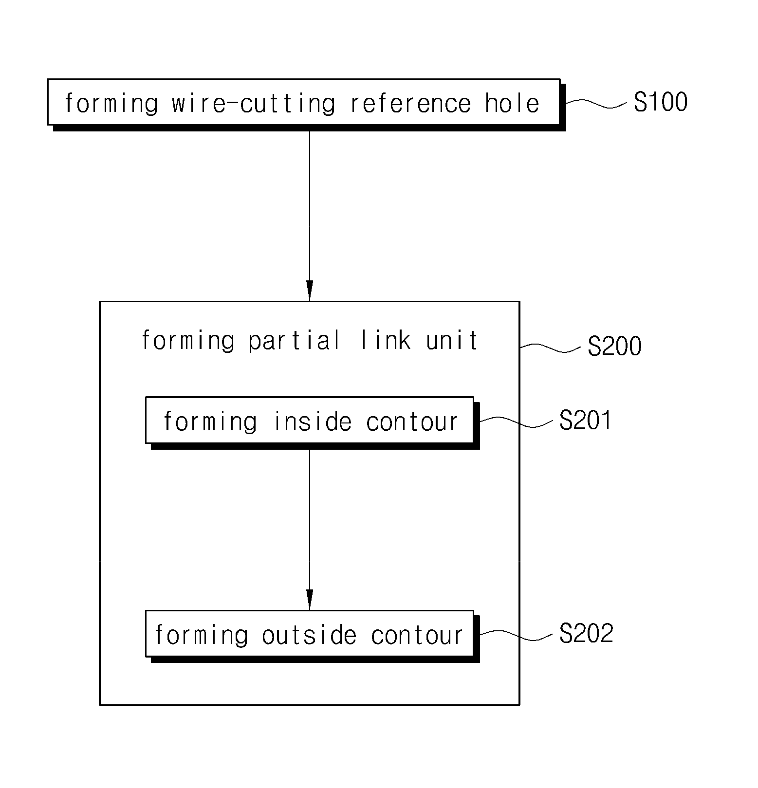
Method of manufacturing master link
a technology of master links and assembly parts, applied in the field of master links, can solve the problems of reducing increasing cutting errors, and comparatively low process speed, and achieve the effect of enhancing the degree of precision and quality of products, and reducing cutting errors in the assembly portion of partial link units
- Summary
- Abstract
- Description
- Claims
- Application Information
AI Technical Summary
Benefits of technology
Problems solved by technology
Method used
Image

Examples
Embodiment Construction
[0024]Hereinafter, a preferred embodiment of the present invention will be described in detail with reference to the attached drawings.
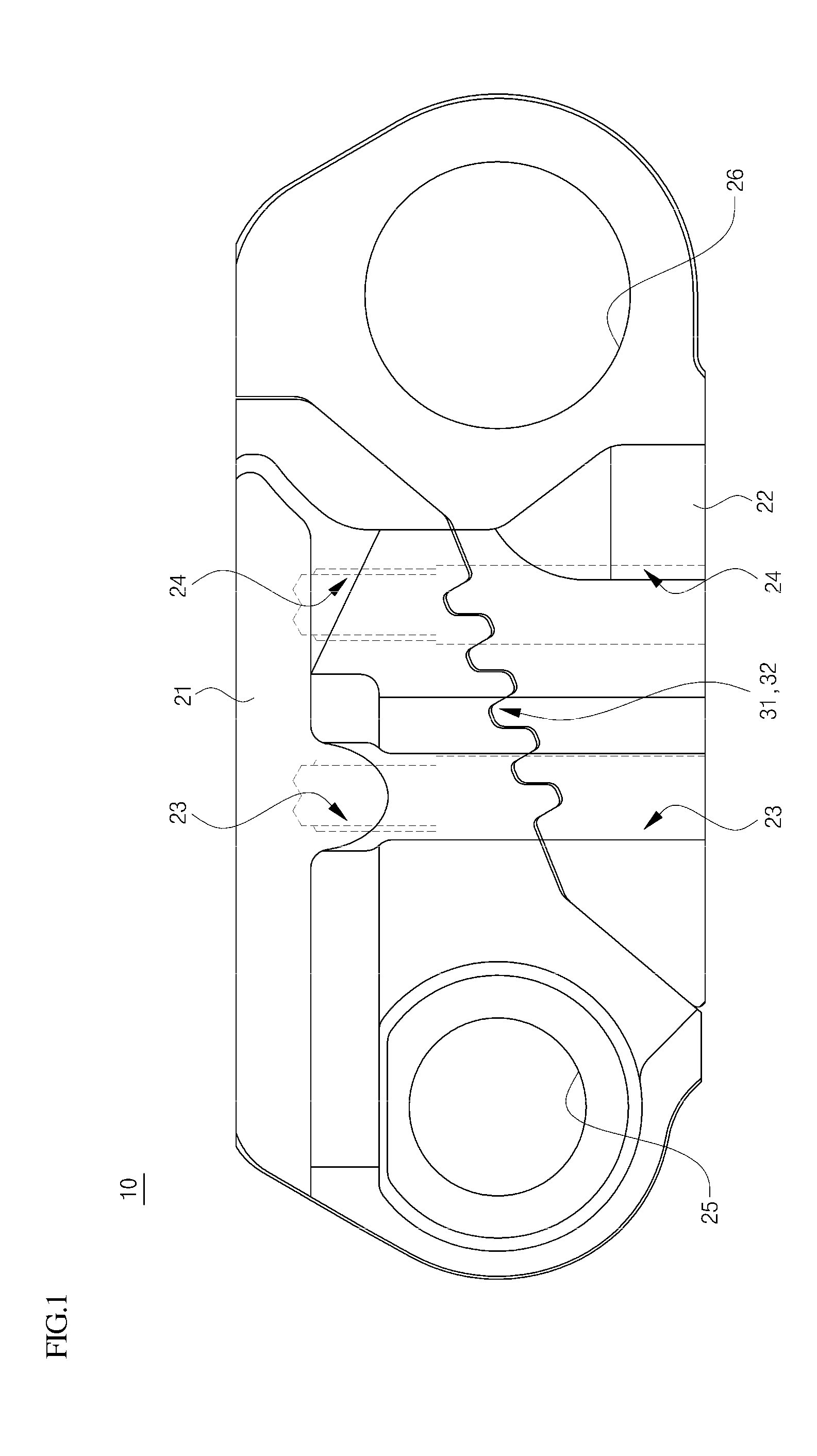
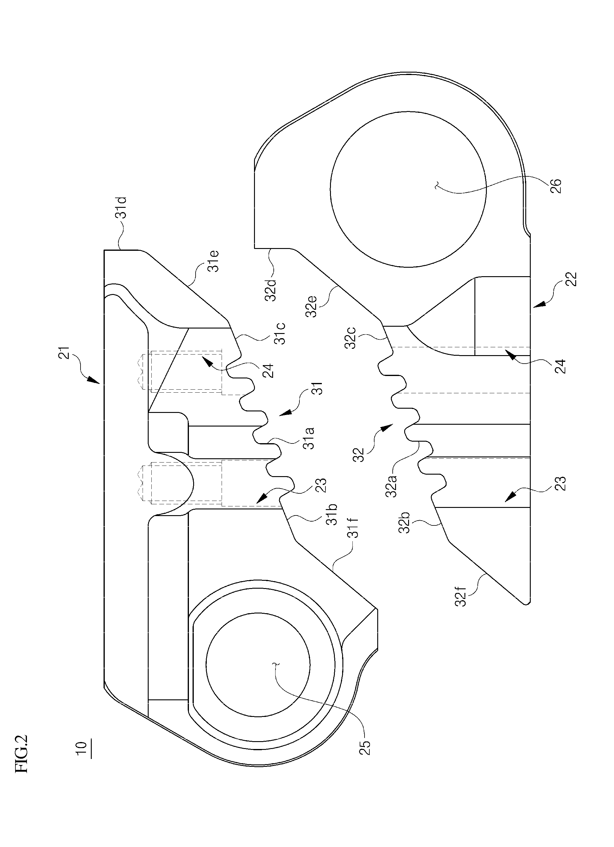
[0025]FIGS. 1 and 2 are views illustrating a master link which connects ends of a track chain links of an endless track to each other.
[0026]As shown in the drawings, the master link 10 includes first and second partial link units 21 and 22. In other words, the first partial link unit 21 and the second partial link unit 22 are separably coupled to each other, thus forming the master link 10. A first assembly portion 31 of the first partial link unit 21 and a second assembly portion 32 of the second partial link unit 22 engage with each other and are coupled to each other by couplers or the like.
[0027]Pin bores 25 and 26, into which pins are coupled, are respectively formed in ends of the first and second partial link units 21 and 22. Coupling holes 23 and 24 are formed in each of the first and second partial link units 21 and 22. The coupling holes 23...
PUM
| Property | Measurement | Unit |
|---|---|---|
| diameter | aaaaa | aaaaa |
| diameter | aaaaa | aaaaa |
| angle | aaaaa | aaaaa |
Abstract
Description
Claims
Application Information