Pressure sensor having a diaphragm

a diaphragm and pressure sensor technology, applied in the field of pressure sensors, can solve the problems of reduced measurement sensitivity, difficult to obtain adequate sensitivity, measurement error, etc., and achieve the effect of suppressing the reduction in measurement sensitivity, and suppressing the reduction of measurement error

Inactive Publication Date: 2014-03-18
YAMATAKE HONEYWELL CO LTD
View PDF27 Cites 9 Cited by
  • Summary
  • Abstract
  • Description
  • Claims
  • Application Information

AI Technical Summary

Benefits of technology

[0013]The use of this structure enables the suppression of the reduction in the measurement sensitivity even when the pressure sensor is miniaturized. That is, in the pressure sensor as set forth in the present invention, a first static pressure gauge is formed at an edge portion of a static pressure diaphragm, and a second static pressure gauge is formed in the center portion of the static pressure diaphragm, and thus the change in resistance that is caused by a deformation resulting from the application of pressure will be positive for one of the two static pressure gauges, and negative for the other. Because of this, it is possible to suppress the reduction in measurement sensitivity in relation to static pressure. Additionally, these two static pressure gauges may be disposed at an edge portion and a center portion of a single static pressure diaphragm, making it possible to reduce to one or two the number of static pressure diaphragms, because, at most, two static pressure diaphragms will be sufficient. This makes it possible to achieve miniaturization of the pressure sensor.
[0014]Additionally, the use of the structure enables the suppression of measurement error due to temperature variations. That is, in the pressure sensor as set forth in the present invention, a first static pressure gauge is formed at an edge portion of a static pressure diaphragm, and a second static pressure gauge is formed in the center portion of the static pressure diaphragm, and thus the change in resistance that is caused by a stress that is produced when there is a change in temperature will be in the same direction for both of the two static pressure gauges. This makes it possible to suppress variations in output due to temperature variations.

Problems solved by technology

As a result, a difference in the ambient measurement temperature may cause measurement error.
However, the measurement sensitivity is reduced when the diaphragm is reduced in size.
Because of this, it is difficult to obtain adequate sensitivity.
In other words, it is difficult to achieve miniaturization of the pressure sensor when the diaphragm is made larger in order to increase the measurement sensitivity.
In this way, there is a problem in that it is difficult to achieve a small high performance pressure sensor.

Method used


Image

  • Pressure sensor having a diaphragm
  • Pressure sensor having a diaphragm
  • Pressure sensor having a diaphragm

Examples


Embodiment Construction

[0037]In the below, specific forms of embodiment wherein the present invention is applied will be explained in detail while referencing the drawings.

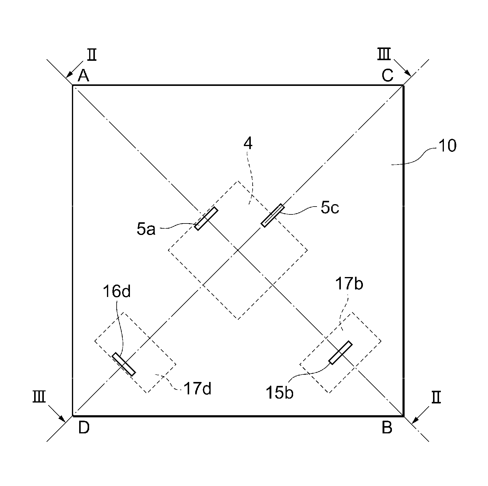
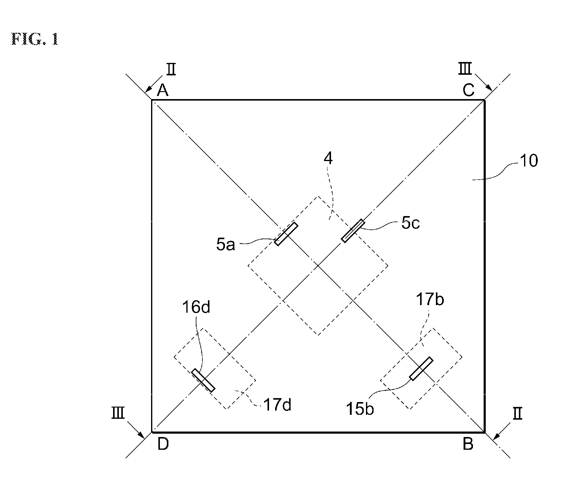
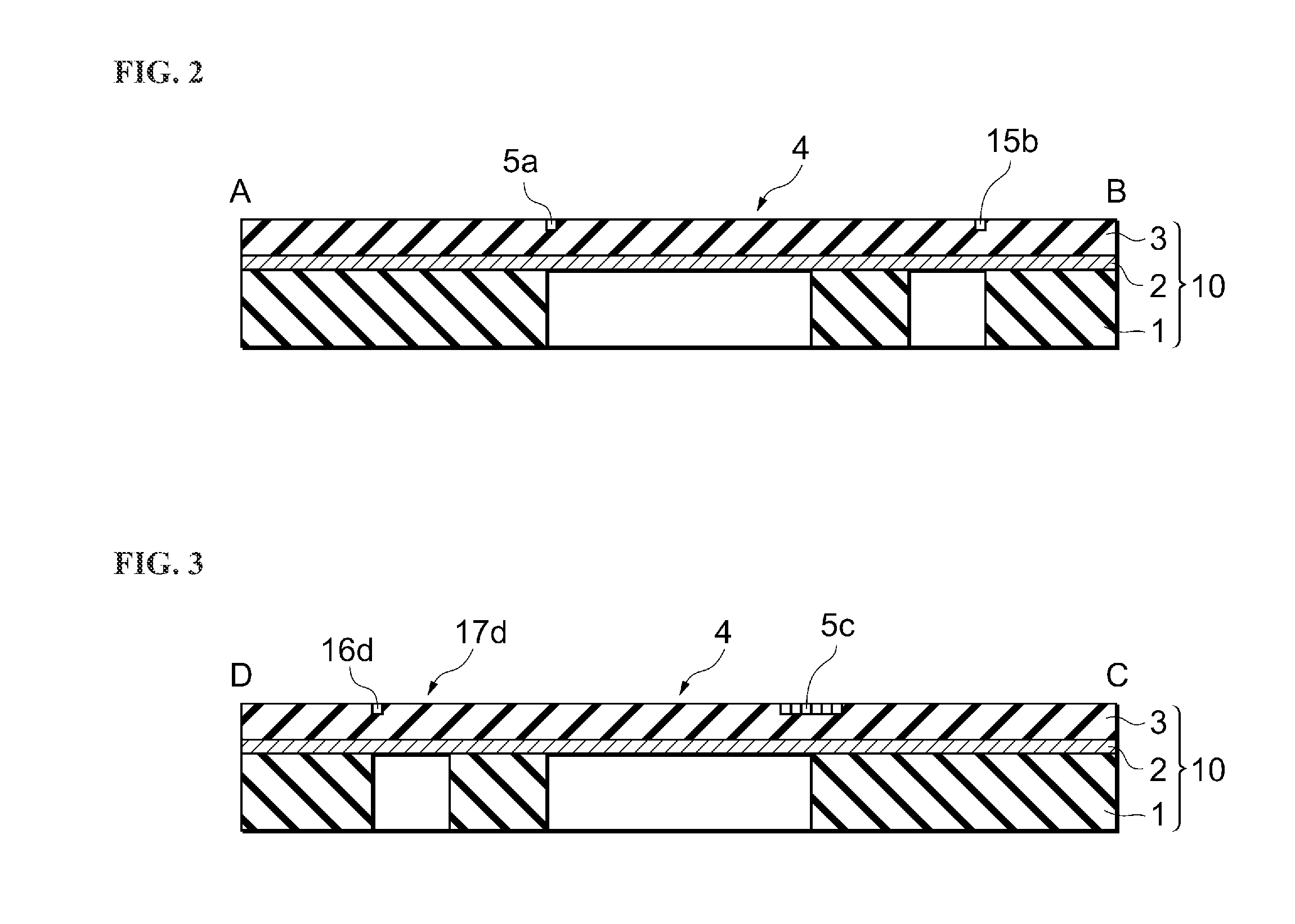
[0038]A pressure sensor as set forth in an example of the present invention will be explained first. FIG. 1 is a top view illustrating the structure of a sensor chip used in a pressure sensor according to the example. FIG. 2 is a cross-sectional diagram along the section II-II in FIG. 1, and FIG. 3 is a cross-sectional diagram along the section III-III. The pressure sensor can be a semiconductor sensor that uses the piezoresistance effect of semiconductors.

[0039]The pressure sensor has a sensor chip 10 that is made out of a semiconductor substrate. The sensor chip 10 is a square shape. As illustrated in FIG. 1, with each of the corners of a square sensor chip 10 defined as A, B, C, and D, the upper-left corner is defined as corner A, the lower-right corner is defined as corner B, the upper-right corner is defined as corner C, and the lo...


PUM

PropertyMeasurementUnit
thicknessaaaaaaaaaa
pressureaaaaaaaaaa
temperatureaaaaaaaaaa

Abstract

A pressure sensor comprising: a sensor chip; a differential pressure diaphragm provided in the center portion of the sensor chip; a differential pressure gauge provided in the differential pressure diaphragm; a static pressure diaphragm provided at the outer peripheral portion of the differential pressure diaphragm; a first static pressure gauge formed at an edge portion of the static pressure diaphragm; and a second static pressure gauge formed at a center portion of the static pressure diaphragm.

Description

CROSS REFERENCE TO RELATED APPLICATIONS[0001]The present application claims priority under 35 U.S.C. §119 to Japanese Patent Application No. 2010-092268, filed Apr. 13, 2010, which is incorporated herein by reference.FIELD OF TECHNOLOGY[0002]The present invention relates to a pressure sensor, and, more specifically, relates to a pressure sensor having a diaphragm.BACKGROUND OF THE INVENTION[0003]Pressure sensors that use a semiconductor piezoresistance effect are small and light, and have high sensitivity, and thus are used broadly in fields such as industrial instrumentation and medicine. In this type of pressure sensor, a diaphragm is formed on a semiconductor substrate. Strain gauges are formed on the diaphragm. The strain gauges are deformed by pressure applied to the diaphragm. The pressure is measured by detecting the changes in resistances in the strain gauges due to the piezoresistance effect.[0004]A pressure sensor wherein a gauge for static pressure detection is positioned...

Claims


Application Information

Patent Timeline
Patent Type & Authority Patents(United States)
IPC IPC(8): G01L15/00G01L13/02
CPCG01L9/0054G01L19/0092G01L19/04G01L15/00G01L9/0047G01L19/02G01L9/065G01L7/08G01L9/04G01L13/06
Inventor TOKUDA, TOMOHISATOJO, HIROFUMIKIDA, NOZOMI
Owner YAMATAKE HONEYWELL CO LTD
Why Eureka
Try Eureka