Light emitter with predefined angular color point distribution

a light emitter and color point technology, applied in the field of light emitters, can solve the problems of reducing system efficiency, difficult to obtain in a simple way, and loss of light in the phosphor converted light source system, and achieve the effect of low cos

Active Publication Date: 2014-03-18
LUMILEDS
View PDF15 Cites 2 Cited by
  • Summary
  • Abstract
  • Description
  • Claims
  • Application Information

AI Technical Summary

Benefits of technology

[0007]It is the object of the invention to provide a possibility to provide a versatile light emitter with a predefined angular color point distribution in conjunction with different desired angular light intensity distributions at low costs.
[0012]According to another preferred embodiment of the invention, the matching element is adapted for adjusting the angular light intensity distribution of the transmitted pump light such that an asymmetric angular color point distribution is achieved. Any asymmetric angular color point distribution is possible, however, the angular color point distribution preferably corresponds to a light distribution with different behavior in a first predetermined range than in a second predetermined range, for instance a light distribution with white color in an angular range between −40° and 40°, with yellow color in an angular range between −40° and −90° and with blue color in an angular range between 40° and 90° is preferred in automotive lamp applications. In such an application, light is white in the forward direction for good visibility, to the left more yellow to avoid the blinding of the driver and more blue to the right in order to see the road marks.
[0015]According to a preferred embodiment of the invention, the phosphor comprises an opening which is adapted for guiding the transmitted pump light to the matching element at least partly without being converted by the phosphor. Preferably, the opening goes from a bottom side to a top side of the phosphor, i.e. in a direction towards the matching element and / or to the output of the light emitter. However, also an opening going from a side surface of the phosphor to a surface of the matching element is possible as long as light is directed to the matching element and / or to the output of the light emitter.
[0019]According to a preferred embodiment of the invention, the matching element comprises a material which shows high photo stability, such as a sol-gel material and / or siloxanes.
[0028]It is an idea of the invention to provide a light emitter or light source, respectively, preferably a high intensity light source, with “tailor-made” multidimensional color point distribution. In automotive lighting applications, a complicated light distribution can be desired for comfort and safety. The invention preferably provides a versatile light source which preferably uses a collimated high intensity light source, such as a laser going preferably through a phosphor, where part of e.g. blue light is preferably converted and / or the transmitted laser beam preferably goes through a refractive and / or diffractive element which preferable creates a desired light distribution for the laser light. It is noted that the superimposition of light, which is preferably generated by partial conversion of the laser beam onto an altered light distribution of the laser beam, preferably gives any color point distribution that is desired. In this way, a perfect or nearly constant white color point as a function of angle can be obtained.
[0032]When a certain intensity distribution, e.g. a hot spot distribution, needs to be created, for this purpose also the laser beam can be shaped to show the desired intensity distribution upon illumination of the phosphor. As a result a special intensity profile of the projected light can be achieved.

Problems solved by technology

However, these suggestions lead to reduced system efficiency while providing a possibility to achieve an almost constant color point.
However, a disadvantage of this solution is losing light in the phosphor converted light source system as a result of back reflection of the blue reflector 3 as shown in FIG. 3b.
This is very difficult to obtain in a simple way by using LEDs.

Method used


Image

  • Light emitter with predefined angular color point distribution
  • Light emitter with predefined angular color point distribution
  • Light emitter with predefined angular color point distribution

Examples


Embodiment Construction

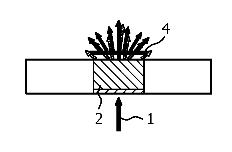
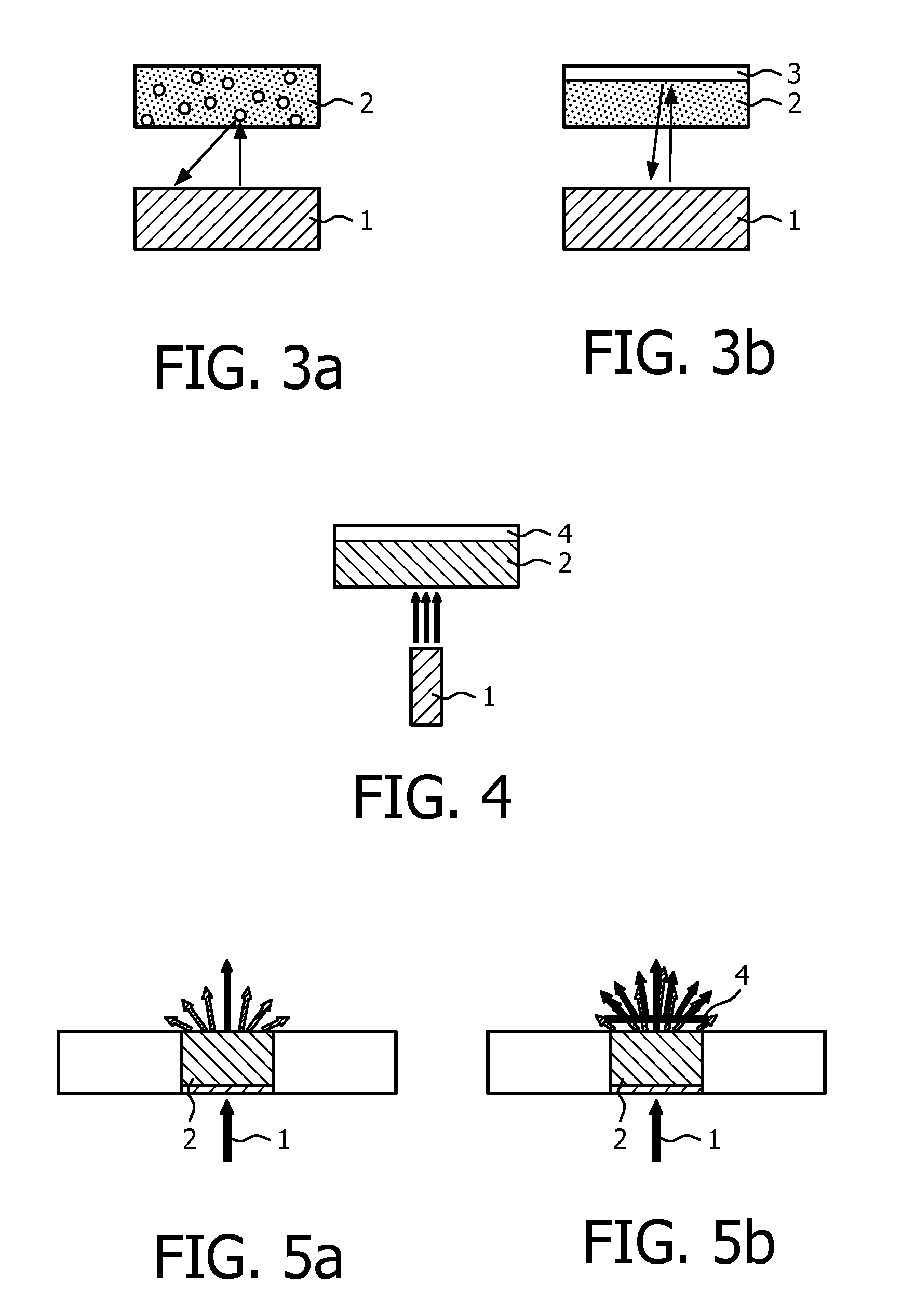
[0054]FIG. 4 shows a light emitter with a predefined angular color point distribution according to a first preferred embodiment of the invention. A pump source 1, here a high intensity pump light source, such as a laser, is used. A highly collimated pump beam, such as laser light, goes through the phosphor 2 showing low light scattering so that the angular light intensity distribution of at least part of the laser light is not altered. Hence, the pump laser is combined with a ceramic phosphor 2. The pump source 1 is adapted for emitting optical radiation to at least part of the phosphor 2. A refractive and / or a diffractive optical component as a matching element 4 is arranged at least partly on top of the phosphor 2. The matching element 4 is a holographic element according to the first preferred embodiment of the invention. The matching element 4 is placed above the phosphor 2 in order to obtain almost any desired light distribution from the laser light as schematically shown in FI...


PUM


Abstract

The invention relates to a light emitter adapted for emitting light with a predefined angular color point distribution, to a method of use for a light emitter in video flash applications, in automotive headlight applications and / or in automotive lamp applications, and to a method, adapted for generating light with a predefined angular color point distribution. The light emitter is adapted for emitting light with a predefined angular color point distribution through an output and comprises a phosphor (2) and a pump source (1), wherein the pump source (1) is adapted for emitting pump light to at least part of the phosphor (2), and the phosphor (2) is adapted for emitting phosphor light by light conversion of absorbed pump light, and wherein a matching element (4) is provided which is arranged at least partly between the phosphor (2) and the output of the light emitter, and which is adapted for adjusting the ratio of the light intensity of the emitted phosphor light emitted by the phosphor (2) towards the output of the light emitter to the light intensity of the transmitted pump light going through the phosphor (2) towards the output of the light emitter. In this way, a versatile light emitter with a predefined angular color point distribution in conjunction with any desired angular light intensity distribution is provided at low costs.

Description

FIELD OF THE INVENTION[0001]The invention relates to a light emitter adapted for emitting light with a predefined angular color point distribution through an output, to a method of use for a light emitter in video flash applications, in automotive headlight applications and / or in automotive lamp applications, and to a method for generating light with a predefined angular color point distribution.BACKGROUND OF THE INVENTION[0002]Document U.S. Pat. No. 7,488,088 B2 describes a light emitting diode lighting device, an LED lighting device for short, and a method that produces high intensity and spatially uniform white light in the near and far fields in a reduced package size that does not significantly heat the surrounding environment, wherein the white light is produced by using a phosphor layer in conjunction with at least one LED.[0003]In different phosphor converted LED applications, such as in camera flash, and in general illumination applications, constant color point as a functi...

Claims


Application Information

Patent Timeline
Patent Type & Authority Patents(United States)
IPC IPC(8): F21V1/00
CPCC09K11/7734C09K11/7774F21K99/00G09F13/20C09K11/7731F21Y2101/00F21V9/16F21S48/1145H01L33/58H01L33/50F21Y2115/10F21S41/16F21V9/30G03H1/2202F21V13/14F21S41/176C09K11/77347C09K11/77348F21K9/20
Inventor HIKMET, RIFAT ATA MUSTAFAVAN BOMMEL, TIESNI, YONGFENG
Owner LUMILEDS
Why Eureka
Try Eureka