
Transmission mode selection based on radio link quality and radio load on the air interface

a radio link quality and radio load technology, applied in adaptive control, wireless commuication services, instruments, etc., can solve the problems of high inefficiency of cl double codeword transmission, severe impact on the total capacity of the telecommunication network, and limited performance of the whole telecommunication system, so as to reduce keep the probability of data loss small , the effect of slow rrc transmission mode reconfiguration

Inactive Publication Date: 2014-03-18
RPX CORP
View PDF7 Cites 2 Cited by
  • Summary
  • Abstract
  • Description
  • Claims
  • Application Information

AI Technical Summary

Benefits of technology

The patent text discusses the use of different transmission modes for improving the performance of wireless communication. These modes include single codeword, double codeword, spatial multiplexing, and others. The proposed method can be applied to both single user and multi-user MIMO networks, as well as cooperative MIMO networks. The text also highlights that in high network load, the UEs will predominantly stay in the diversity transmission mode, which can mitigate the limitations of the PDCCH. This allows for a higher capacity of the network without affecting the performance of the PDCCH. Overall, the patent text presents a technical solution for improving wireless communication performance.

Problems solved by technology

This has severe impact on the total capacity of the telecommunication network, i.e. how many UEs can be scheduled per transmission time interval (TTI) without blocking the PDCCH.
Thereby, the performance of the whole telecommunication system is limited.
Hence, always staying with all UEs in the MIMO transmission modes OL Spatial Multiplexing respectively CL Double Codeword Transmission is highly inefficient and costs capacity and performance due to limits of the PDCCH.
Unfortunately reconfigurations or reselections of the transmission mode are performed in LTE via slow Radio Resource Control (RRC) messaging on a timescale of approximately 50 ms to 100 ms.
Therefore, it is not feasible to reconfigure or to reselect the transmission mode as fast as a “dynamic MIMO switch” within a single or at least several TTIs of 1 ms each.

Method used


Image

  • Transmission mode selection based on radio link quality and radio load on the air interface
  • Transmission mode selection based on radio link quality and radio load on the air interface
  • Transmission mode selection based on radio link quality and radio load on the air interface

Examples


Embodiment Construction

[0065]It should be noted that the term “comprising” does not exclude other elements or steps and “a” or “an” does not exclude a plurality. Also elements described in association with different embodiments may be combined. It should also be noted that reference signs in the claims should not be construed as limiting the scope of the claims.

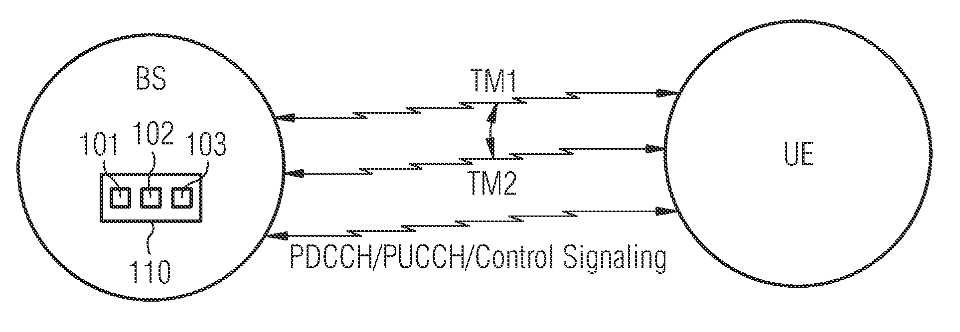
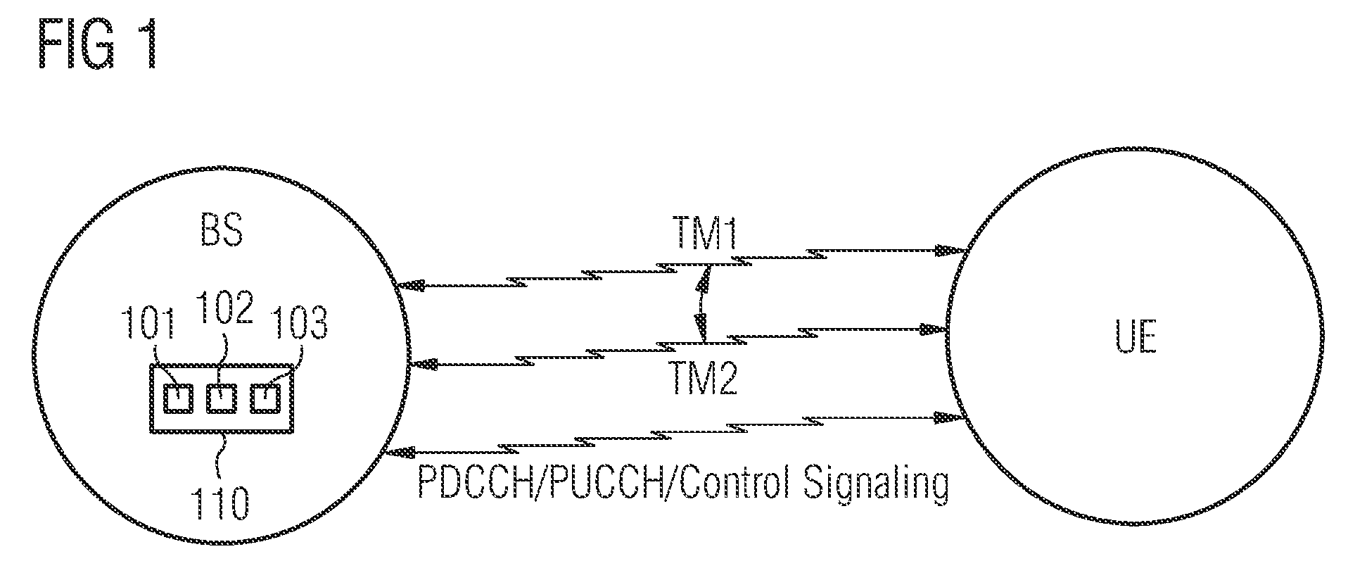
[0066]FIG. 1 shows in a schematic representation a radio link extending between a base station BS and a user equipment UE. For transmitting data between the BS and the UE two different transmission modes, a first transmission mode TM1 and a second transmission mode TM2, can be used.

[0067]The base station BS comprises a control device 110. The control device 110 comprises a first determining unit 111 for determining the actual quality of the radio link and a second determining unit 112 for determining the radio load in a non depicted telecommunication network cell, to which the base station BS and the user equipment UE are assigned to. The control d...


PUM


Abstract

It is described a method for selecting a transmission mode for a radio data transfer between a user equipment and a base station of a telecommunication network. The method includes (a) determining the quality of a radio link, which extends between the user equipment and the base station, (b) determining the radio load within the telecommunication network, and (c) selecting a transmission mode based on the quality of the radio link and on the radio load. It is further described a control device for selecting a transmission mode for a radio data transfer between a user equipment and a base station and a computer program for controlling the described transmission mode selection method.

Description

FIELD OF INVENTION[0001]The present invention relates to the field of radio telecommunication networks. In particular, the present invention relates to a method for selecting a transmission mode for a radio data transfer between a user equipment and a base station of a telecommunication network. Further, the present invention relates to a control device for selecting a transmission mode for a radio data transfer between a user equipment and a base station of a telecommunication network. Furthermore, the present invention relates to a computer program for controlling the described transmission mode selection method.ART BACKGROUND[0002]In modern radio telecommunication networks such as 3GPP Long Term Evolution (LTE) networks it is known to use different transmission modes for the communication between a mobile end terminal, which is also called user equipment (UE), and a base station (BS), which according to the LTE nomenclature is typically called enhanced NodeB (eNB). Thereby the se...

Claims


Application Information

Patent Timeline
Patent Type & Authority Patents(United States)
IPC IPC(8): H04W4/00
CPCH04B7/0452H04B7/0689H04B7/0697
Inventor BALL, CARSTENPAYER, WOLFGANG
Owner RPX CORP
Learn More