Communication and sensor techniques for underwater radio communication

a radio communication and sensor technology, applied in the field of advanced underwater radio frequency communication and sensor networks, can solve the problems of limited performance of conventional rf communication schemes in water, difficult implementation of radio signals for long distance undersea communication, and severe limitations in the ability to communicate over distance in water, so as to improve the coupling of electromagnetic energy, reduce power losses, and improve the effect of impedance matching efficiency

Active Publication Date: 2018-07-12
SALTENNA LLC
View PDF2 Cites 7 Cited by
  • Summary
  • Abstract
  • Description
  • Claims
  • Application Information

AI Technical Summary

Benefits of technology

[0016]These methods, apparatuses, and/or systems provide significant advantages over prior art existing-art underwater RF antennas. Particularly, the present invention utilizes an impedance matching enclosure filled with an impedance matching fluid around a RF antenna. In some embodiments, the impedance matching fluid is de-ionized water. This enables improved coupling of the electromagnetic energy to the surrounding salt-water medium via more efficient impedance matching, while it also drastically reduces power losses due to the high ionic conductivity of seawater in the immediate vicinity of the antenna. Further, RF antenna configurations of the present invention become nearly ten times more compact due to the high relative dielectric constant (˜80) of the de-ionized water, a

Problems solved by technology

Radio signals are difficult to implement for long distance undersea communication because they are rapidly attenuated in fresh, brackish, and salt water.
Performance of conventional RF communication schemes in water are limited by the relatively small RF skin depth, which may be estimated as:
This signal attenuation severely limits the ability to communicate over distance in water.
For example, at ν=20 MHz the skin depth in seawater is 6 cm, so conventional implementations of three-dimensional RF communication schemes are impractical in sa

Method used


Image

  • Communication and sensor techniques for underwater radio communication
  • Communication and sensor techniques for underwater radio communication
  • Communication and sensor techniques for underwater radio communication

Examples


Embodiment Construction

[0030]In the following description, for the purposes of explanation, numerous specific details are set forth in order to provide a thorough understanding of the embodiments of the invention. It will be appreciated, however, by those having skill in the art that the embodiments of the invention may be practiced without these specific details or with an equivalent arrangement. In other instances, well-known structures and devices are shown in block diagram form in order to avoid unnecessarily obscuring the embodiments of the invention.

[0031]Structure and Operation of a Communication and Sensor Network

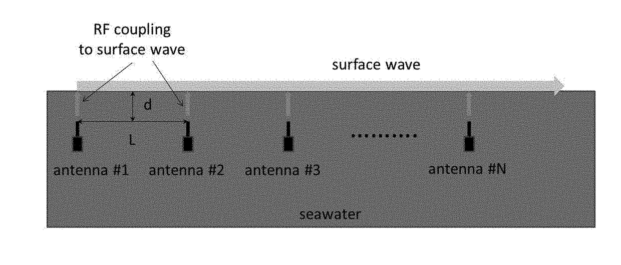
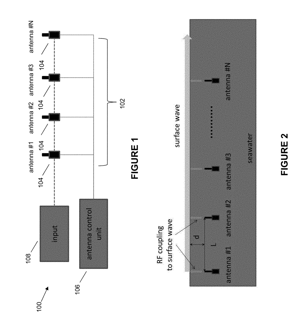
[0032]FIG. 1 shows a communication and sensor network 100 in accordance with the present invention which comprises a mechanical antenna array 102 comprising a plurality of antenna elements 104 to receive and transmit radio frequency (RF) signals. The antenna array 102 may be defined as a set of individual antenna elements 104 used for transmitting and / or receiving RF signals, connected to...


PUM


Abstract

A linear array of underwater radio frequency (RF) antennas is implemented, which emit surface electromagnetic waves propagating along either water-air or water-seafloor interface. The phase difference Δϕ between neighboring antennas defines the overall beam direction, while the so-formed directional beam intensity remains almost constant near the antenna array due to the largely two-dimensional character of beam propagation. By adjusting the phase difference Δϕ, the narrow two-dimensional surface beam may be sent in any direction over 360°, thus enabling targeted RF communication with any desired object located near the said interface. An impedance matching enclosure filled with an impedance matching fluid may also be utilized surrounding the antennas to reduce antenna dimensions and improve coupling of electromagnetic energy to the surrounding salt water medium, thereby improving underwater radio communication performance.

Description

[0001]This application claims priority to U.S. Provisional Patent Application No. 62 / 443,075 filed on Jan. 6, 2017 and U.S. Provisional Patent Application No. 62 / 447,079 filed on Jan. 17, 2017, which are incorporated by reference herein in its entirety.FIELD OF THE INVENTION[0002]The present invention relates generally to the field of advanced underwater radio frequency communication and sensor networks for salt and brackish water environments More particularly, the present invention improves underwater radio communication distance and power in communication and sensor networks via formation of weakly decaying directional surface radio beams, and reduces the physical antenna dimensions and improves underwater radio communication distance and radiated power via simultaneous impedance matching and electromagnetic isolation of the underwater antenna, and will be described in connection with such utility, although other utilities are contemplated.BACKGROUND OF THE INVENTION[0003]Radio s...

Claims


Application Information

Patent Timeline
IPC IPC(8): H04B13/02H04B7/06
CPCH04B13/02H04B7/0617
Inventor SMOLYANINOV, IGOR
Owner SALTENNA LLC
Why Eureka
Try Eureka