
Transceiver apparatus and method for efficient retransmission of high-speed packet data

a data transceiver and packet data technology, applied in the field of data transceiver apparatus and method in a cdma (code division multiple access) mobile communication system, can solve the problems of difficult to determine which technique is optimal for a given system, impedes a high-speed, high-quality radio data service, and difficult to adapt to the channel environment. achieve the effect of improving the performance of the radio communication system

Inactive Publication Date: 2010-03-09
SAMSUNG ELECTRONICS CO LTD
View PDF17 Cites 14 Cited by
  • Summary
  • Abstract
  • Description
  • Claims
  • Application Information

AI Technical Summary

Benefits of technology

[0025]It is, therefore, an object of the present invention to provide a data transceiver apparatus and method for improving performance of a radio communication system.

Problems solved by technology

A principal factor that impedes a high-speed, high-quality radio data service lies in the radio channel environment.
The radio channel environment frequently changes due to a variation in signal power caused by white noise and fading, shadowing, Doppler effect caused by the movement of and the frequent change in speed of a UE (User Equipment), and interference caused by other users and multipath signals.
However, the HARQ should be considered in the light of not only the performance but also the system complexity, such as a buffer size and signaling of the receiver.
As a result, it is difficult to determine which technique is optimal for a given system.
However, as described above, a high-speed data transmission channel may subject to a change in channel environment even for an HARQ period due to the change in the number of UEs in a cell and the Doppler shift.
Therefore, maintaining the modulation technique and the coding rate used at the initial transmission contributes to a reduction in the system performance.
However, the use of the variable TTI increases complexity of realization and signaling.
Although this technique can decrease BER by retransmitting an unspecified part of the randomly interleaved data and combining the retransmitted partial data with the initially transmitted full packet, an improvement in a frame error rate (FER) is restrictive.

Method used


Image

  • Transceiver apparatus and method for efficient retransmission of high-speed packet data
  • Transceiver apparatus and method for efficient retransmission of high-speed packet data
  • Transceiver apparatus and method for efficient retransmission of high-speed packet data

Examples


second embodiment

of Transmitter

[0066]FIG. 5 illustrates a structure of a transmitter for a CDMA mobile communication system according to another embodiment of the present invention. Like the embodiment shown in FIG. 4, FIG. 5 also shows only the elements arranged between the buffer and the modulator in the transmitter.

[0067]Referring to FIG. 5, coded bits generated by encoding input data at a mother coding rate of a turbo encoder (not shown) are stored in a buffer 502. The coded bits are properly punctured by a puncturer 504 according to information on a coding rate and a selected HARQ type, provided from a controller 520. The puncturer 504 uses a puncturing pattern for puncturing the coded bits according to the HARQ type. When the HARQ type is CC or PIR, an output of the puncturer 504 is comprised of a systematic sub-packet having only the systematic bits and a parity sub-packet having only the parity bits at each transmission. Here, when the HARQ type is CC, the parity sub-packet output from the p...

first embodiment

of Receiver

[0076]FIG. 6 illustrates a structure of a receiver corresponding to the transmitter of FIG. 5, according to an embodiment of the present invention. In FIG. 6, a despreader 602, a demodulator 606 and a controller 620 are provided with information on a coding rate, a modulation technique, a Walsh code used, a redundancy packet number, and the number of retransmissions over a downlink control channel, and the elements perform the following operations based on the provided information.

[0077]Referring to FIG. 6, a received data symbol, which was frequency-spread by the transmitter of FIG. 5 with multiple Walsh codes before being transmitted, is despread into a plurality of transmission symbol streams by a despreader 602 with the multiple Walsh codes used by the transmitter. The receiver can be provided with the multiple Walsh codes used in the transmitter based on Walsh code information signaled over a downlink channel. The transmission symbol streams despread by the despreade...

first embodiment (

1. First Embodiment (Coding Rate ½, PIR)

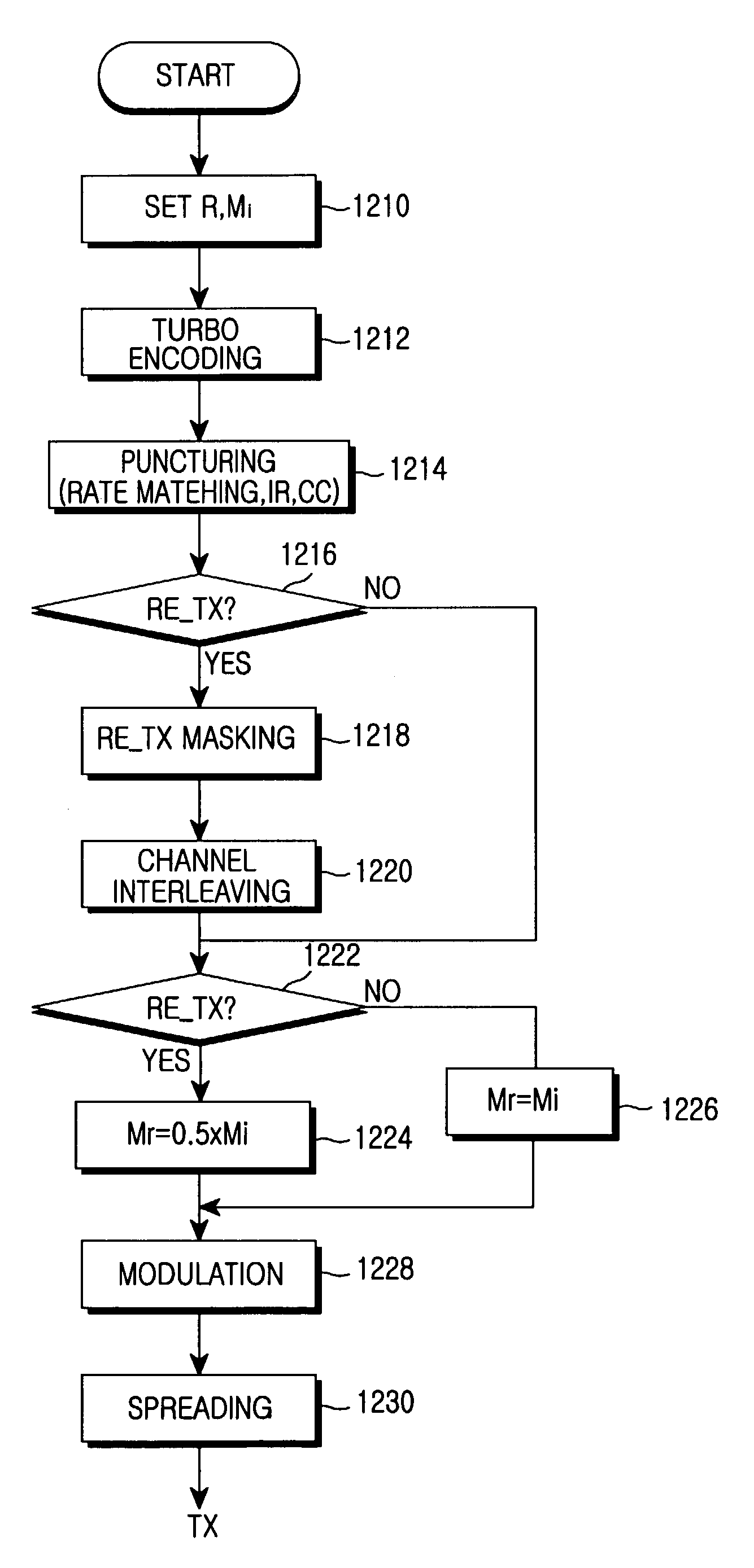
[0093]In the first embodiment, a coding rate is ½ and PIR is used as the HARQ. In addition, it is assumed that modulation techniques at initial transmission and retransmission are 16QAM and QPSK, respectively. Further, it is assumed that the number of Walsh codes used at retransmission is equal to the number of Walsh codes used at initial transmission.

[0094]In this embodiment, only three parity sub-packets will be taken into consideration, for the sake of convenience. In each table illustrated in FIGS. 7 to 11B, “O” means a sub-packet transmitted when a modulation technique at retransmission is identical to a modulation technique at retransmission, while “X” represents a sub-packet selected when a modulation technique is changed at retransmission according to an embodiment of the present invention.

[0095]FIG. 7 illustrates sub-packets that can be selected when a modulation technique is changed during retransmission in the retransmission mask se...


PUM


Abstract

A method for retransmitting coded bits by a transmitter in response to a retransmission request from a receiver in a mobile communication system. The method comprises determining a modulation technique to be used at retransmission as a modulation technique having a lower modulation order than a modulation technique used at initial transmission; determining a puncturing pattern according to an HARQ (Hybrid Automatic Repeat Request) type, and selecting as many coded bits as the number of coded bits that can be symbol-mapped by the determined modulation technique, among the coded bits punctured by the determined puncturing pattern; and symbol-mapping the selected coded bits by the determined modulation technique, and transmitting the symbol-mapped coded bits to the receiver.

Description

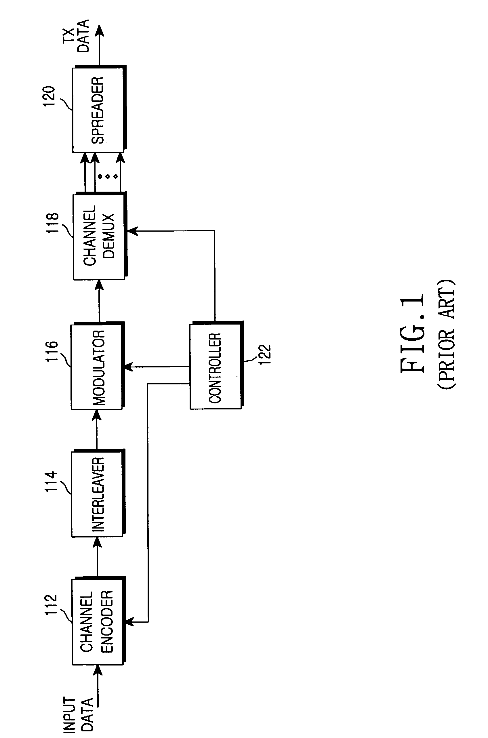
PRIORITY[0001]This application claims priority to an application entitled “Transceiver Apparatus and Method for Efficient Retransmission of High-Speed Packet Data” filed in the Korean Industrial Property Office on Nov. 2, 2001 and assigned Serial No. 2001-68316, the contents of which are hereby incorporated by reference.BACKGROUND OF THE INVENTION[0002]1. Field of the Invention[0003]The present invention relates generally to a data transceiver apparatus and method in a CDMA (Code Division Multiple Access) mobile communication system, and in particular, to an apparatus and method for transmitting and receiving data using a variable modulation technique during retransmission.[0004]2. Description of the Related Art[0005]Presently, the mobile communication system has evolved from an early voice-based communication system to a high-speed, high-quality radio data packet communication system for providing a data service and a multimedia service. In addition, a 3rd generation mobile communi...

Claims


Application Information

Patent Timeline
Patent Type & Authority Patents(United States)
IPC IPC(8): H03M13/00H03M13/03H04L1/16H04B7/26H04J13/00H04LH04L1/00H04L1/18H04W4/00H04W28/04H04W28/18
CPCH04L1/0003H04L1/0009H04L1/0026H04L1/0066H04L1/1893H04L1/0071H04L1/1819H04L1/1887H04L1/0069H04L1/1845H04L1/16H04W40/22
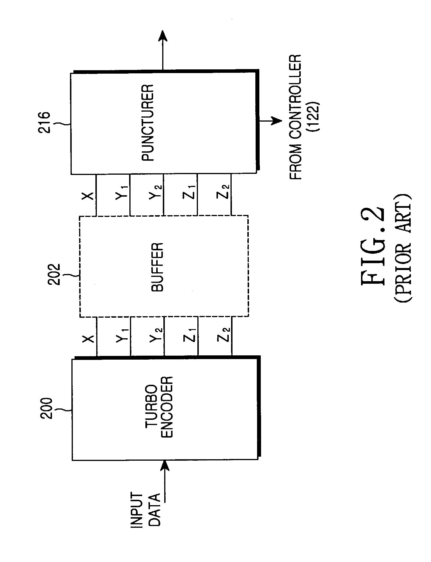
Inventor MOON, YONG-SUKKIM, HUN-KEEYOON, JAE-SEUNG
Owner SAMSUNG ELECTRONICS CO LTD
Learn More